 |
Figure 01
|
For EC&M Magazine
By Mike Holt, NEC® Consultant
Do you understand the requirements for a safe sign installation?
Article 600 covers the installation of conductors, equipment, and field wiring for electric signs and outline lighting. It also covers retrofit kits.
Outline lighting is an arrangement of incandescent lamps or electric discharge lighting to outline or call attention to certain features, such as the shape of a building or the decoration of a window [Article 100].
Informational Note: Sign and outline lighting systems can include high intensity discharge (HID), fluorescent, incandescent, LEDs, electroluminescent, and/or inductance lighting. Also, some systems use cold cathode neon tubing.
Neon art forms are subsets of electric signs and outline lighting. If installed and not attached to an enclosure or sign body, they’re considered skeleton tubing for Article 600 purposes. But if neon tubing is attached to an enclosure or sign body, it’s considered sign or outline lighting for Article 600 purposes.
Branch circuits
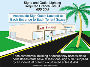
Each commercial building or occupancy accessible to pedestrians must have an accessible outlet at the entrance of each tenant space, and be supplied with an individual branch circuit rated at least 20A [600.5(A)].Figure 01
Branch circuits that supply:
• Signs are continuous loads [600.5(B)].
• Neon tubing installations must be rated 30A or less.
• Other signs and outline lighting systems must be rated 20A or less.
The wiring for a sign must terminate in the sign or outline lighting enclosure, box, or conduit body [600.5(C)(1)]. Poles used to support signs can contain the sign circuit conductors, if the installation complies with 410.30(B) [600.5(C)(3)].
Disconnecting means
Each circuit for a sign, outline lighting system, or skeleton tubing must be controlled by an externally operable switch or circuit breaker that will open all ungrounded conductors.
Where the circuit is a multiwire branch circuit, the switch or circuit breaker must open all ungrounded conductors of the circuit simultaneously per 210.4(B).
Locate the disconnect in a way that allows service or maintenance personnel to have local control of it. You can locate the disconnect at the sign entrance point, within sight of the sign, or within sight of the controller [600.6(A)].
Entrance point
If locating the disconnect at the entrance point, the disconnect must be where the conductors enter the sign enclosure, sign body, or pole per 600.5(C)(3). It must open all ungrounded conductors of the circuit.
But the disconnect isn’t required for:
• Conductors that pass through a sign in a Chapter 3 raceway or metal jacketed cable identified for the location [600.6(A)(1) Ex. 1].
• Circuits that supply an internal panelboard in a sign enclosure or sign body if the circuit conductors are enclosed in a Chapter 3 raceway or metal jacketed cable identified for the location. A permanent field applied warning label must be on the raceway or metal cable at or near the point of entry. It must have sufficient durability to withstand the environment involved, comply with 110.21(B), and be visible during servicing. It must identify the location of the disconnect for the energized circuit conductors. The disconnect must be capable of being locked in the open position with provisions for locking to remain in place whether the lock is installed or not [110.25]. [600.6(A)(1) Ex. 2].
Within sight of the sign
If locating the disconnect within sight of the sign, it might not be visible from some energizable section of the sign or outline lighting. In such a case, the disconnect must be lockable with provisions for locking to remain in place whether the lock is installed or not [110.25].
A permanent field applied warning label is required on the sign at a location visible during servicing. It must have sufficient durability to withstand the environment involved, comply with 110.21(B), and identify the location of the disconnect.
Within sight of the controller
If locating the disconnect within sight of the controller, and the signs or outline lighting systems are operated by external electronic or electromechanical controllers, ensure each disconnect is [600.6(A)(3)]:
• Within sight of (or in) the same enclosure with the controller.
• Capable of disconnecting the sign or outline lighting and the controller from all ungrounded supply conductors.
• Lockable with provisions for locking to remain in place whether the lock is installed or not [110.25].
If the disconnect isn’t within sight of the controller, a permanent field applied warning label must be applied to the controller at a location visible during servicing. It must have sufficient durability to withstand the environment involved, comply with 110.21(B), and identify the location of the disconnect.
Grounding
Metal equipment of signs, outline lighting systems, and skeleton tubing must be connected to the circuit equipment grounding conductor (EGC) of a type recognized in 250.118 [600.7(A)(1)]. Size the EGC of the wire type per 250.122, based on the rating of the overcurrent protection device. EGC connections must be made per 250.130, in a method specified in 250.8 [600.7(A)(2)].
Auxiliary grounding electrodes aren’t required for signs and outline lighting. But if installed, they must comply with 250.54.
Don’t use the earth as the effective ground-fault current path required by 250.4(A)(4) and 250.4(A)(5). The contact resistance of a grounding electrode to the earth is high, so insignificant ground-fault current returns to the electrical supply source via the earth. Using the earth as the effective ground-fault current path means the circuit overcurrent protection device probably won’t open to clear a ground fault.
Bonding
Metal parts of signs and outline lighting systems must be bonded to the transformer or power-supply EGC [600.7(B)(1)]. But the metal parts of a section sign or outline lighting system supplied by a remote Class 2 power supply don’t have to be connected to an EGC. Bonding connections must be made per 250.8 [600.7(B)(2)].
Listed flexible metal conduit or listed liquidtight flexible metal conduit for secondary circuit conductors for neon tubing can be used as a bonding means if the total cumulative length of the conduit doesn’t exceed 100 ft [600.7(B)(4)].
Location
Unless mechanically protected from physical damage, a sign or outline lighting system must be at least 14 ft above areas accessible to vehicles [600.9(A)]. Neon tubing used for signs, decorative elements, skeleton tubing, or art forms must be protected from physical damage where readily accessible to pedestrians [600.9(B)].
Signs and outline lighting systems must be installed so adjacent combustible materials aren’t subjected to temperatures that exceed 194 DegF. An incandescent or HID lamp or lampholder must have at least 2 in. of spacing between it and combustible materials [600.9(C)].
Signs and outline lighting systems installed in wet locations must be weatherproof and must have drain holes [600.9(D)].
Goin’ mobile
Portable or mobile signs must be adequately supported and readily movable without the use of tools. An attachment plug is required for each portable or mobile sign [600.10].
Portable or mobile signs in wet or damp locations must have cords that are junior hard-service or hard-service types, as designated in Table 400.4, with an EGC. They also must have listed manufacturer-installed GFCI protection.
To prevent the use of extension cords, the flexible cord on a portable or mobile sign installed in a dry location can be up to 15 ft long [600.10(D)].
Class 2
Ballasts, transformers, electronic power supplies, and Class 2 power sources must be self-contained or enclosed in a listed sign body or listed separate enclosure [600.21]. They must also be accessible and securely fastened in place.
Class 2 power supplies and power sources must be listed for use with electric signs and outline lighting systems or be a component in a listed sign [600.24]. Metal parts of the Class 2 power sources must be connected to the circuit EGC supplying the power source.
Return path reminder
A single bonding deficiency can render metal parts of a sign or near a sign dangerous. Ensure you have a solid, mechanically reliable return path for undesired current. Take care not to create bonding deficiencies by committing installation errors such as using building steel as the EGC or not bonding around a concentric knockout [250.92(B)].
|