|
For EC&M Magazine
By Mike Holt, NEC® Consultant
Do you know the NEC requirements for sizing junction boxes and pull boxes for conductor sizes 4 AWG and larger?
(1)(a)(b).jpg)
Figure 01
|
 |
|
Figure 01
|
For EC&M Magazine
By Mike Holt, NEC® Consultant
Don’t confuse overload protection with short-circuit and ground-fault protection.
Motors and their associated equipment must be protected against both overload and overcurrent (short circuit or ground fault). This function is usually split, with separate devices for overload protection and for short-circuit / ground-fault protection.
Part III of Article 430 contains the requirements for motor branch-circuit overload protection. Part IV contains the requirements for motor branch-circuit short-circuit and ground-fault protection.
The actual current drawn by the motor depends upon the load and the actual operating voltage at the motor terminals. If the load increases, the current also increases, or if the motor operates at a voltage below its nameplate rating, the operating current increases.
You size the overload devices based on the motor nameplate current rating per 430.31 [430.6(A)(2)]. The motor nameplate full-load ampere rating is identified as “full-load amperes” (FLA). The FLA rating is the current in amperes the motor draws while producing its rated horsepower load at its rated voltage, based on its rated efficiency and power factor.
Motors built to operate at less than 1,200 RPM or that have high torques may have higher full-load currents. Multispeed motors have full-load current varying with speed. In these cases, you must use the nameplate current ratings.
Section 430.6(A)(1) Ex 3: For a listed motor-operated appliance, use the motor full-load current marked on the nameplate of the appliance (instead of the horsepower rating on the appliance nameplate) to determine the ampacity or rating of the disconnecting means, the branch-circuit conductors, the controller, and the branch-circuit short-circuit and ground-fault protection.
Branch-circuit conductors to a single motor used for continuous duty must have an ampacity of at least 125 percent of the motor’s full-load current (FLC) as listed in Tables 430.247 through 430.250 [430.6(A)(1) and 430.22]. When selecting motor current from one of these tables, the last sentence above each table allows us to use the ampacity columns for a range of system voltages without any adjustment. You select the actual conductor size from Table 310.15(B)(16) according to the terminal temperature rating (60DegrC or 75DegrC) of the equipment [110.14(C)(1)].
Motor applications are continuous duty unless the nature of the control or apparatus the motor drives is designed so the motor won’t operate continuously under load [Table 430.22(E) Note]. When a motor isn’t continuous duty because of this type of application, size the conductors using the percentages of Table 430.22(E).
The motor full-load current (FLC) is from the FLC Tables 430.247 through 430.250 [430.6(A)(1)]. That isn’t the same thing as the motor full-load amperes (FLA), which is the motor’s nameplate rating [430.6(A)(2)].
When a motor is used for other than continuous duty, use the nameplate current rating percentages of Table 430.22(E) for conductor sizing [430.22(E)].
Feeder sizing
Conductors that supply several motors must have an ampacity of at least [430.24]:
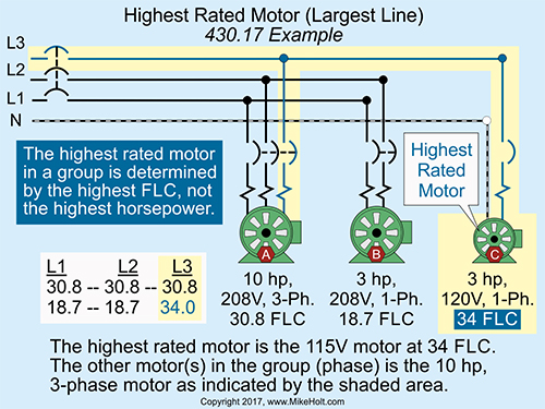
(1) 125 percent of the highest rated motor FLC [430.17], plus
(2) The sum of the FLCs of the other motors in the group (on the same line). Find the motor FLC using the NEC FLC Tables [430.6(A)(1)].
The highest rated motor is based on the motor with the highest full-load current [430.17]. The “other motors in the group” value (on the same line) is determined by balancing the motors’ FLCs on the feeder being sized, then selecting the line that has the highest rated motor.Figure 01
Overcurrent protection
Overcurrent is current greater than the rated current of the equipment or conductors, resulting from an overload, short circuit, or ground fault. In motor circuits, the overcurrent protection function is commonly divided into two separate components; one provides short-circuit and ground-fault protection and the other provides overload protection. Short circuits and ground faults result from faults in the wiring, so they can carry large amounts of current.
Overloads aren’t fault conditions, but just the result of excessive current in the circuit. Overload is the condition where current exceeds the equipment ampere rating. The subsequent overheating can damage equipment. Overload protection doesn’t protect against short circuits or ground-fault currents. Overload protection devices (OLs) protect motors, motor control apparatus, and motor branch-circuit conductors against excessive heating due to motor overloads and failure to start.
It’s possible for a motor to become so hot it will burn out or start a fire. Some causes of overload are:
- Low voltage.
- Locked rotor.
- Undersized motor.
- Bad bearings.
- Single-phasing (one conductor of a three-phase circuit fails, causing it to run on two phases).
Overload devices must have enough time delay to stay closed during the high starting current.
Short-circuit and ground-fault protection
Branch-circuit short-circuit and ground-fault protection devices protect the motor, the motor control apparatus, and the conductors against short circuits or ground faults. They don’t protect against an overload [430.51]. Short-circuit or ground-fault protection is designed for fast current rise, short duration, and fast response time.
The short-circuit and ground-fault protection device required for motor circuits isn’t the same thing as the ground-fault circuit-interrupter (GFCI) protection required for personnel [210.8], temporary wiring for receptacles [590.6], or ground-fault protection installed on feeders [215.9 and 240.13] or services [230.95].
Generally, the motor overload device is part of the motor starter or variable frequency drive (VFD). However, a separate overload device like a dual-element fuse can be used [430.32(A)(1)]. If fuses are used, a fuse must be installed for each ungrounded conductor [430.36 and 430.55].
Overload protection sizing
Different rules apply, depending upon the motor nameplate service factor (SF) rating. Motor service factors can be thought of as safety factors. The service factor indicates how much the motor capacity can be exceeded for short periods without overheating. This is important where loads vary and may peak slightly above the rated torque.
A service factor of 1.15 means the motor is designed to periodically operate at 115 percent of its rated horsepower. A standard design B motor with a service factor of 1.15 can operate at 15 percent more than its rated output without overheating. Service factors should be used sparingly as safety margins because if a motor operates continuously above its rated output it will have a short life.
Motors with a nameplate SF rating of 1.15 or more must have their overload protection device sized no more than 125 percent of the motor nameplate current rating [430.6(A)(2)].
In a case where the sensing element or setting, or sizing of the motor overload device, isn’t sufficient to allow the motor to start or to carry the load, the overload element setting or sizing can be increased, but not to exceed 140 percent for motors with a marked service factor of 1.15 or greater [430.32(C)].
Motors with a nameplate temperature rise rating not over 40 De°grC must have the overload protection device sized no more than 125 percent of the motor nameplate current rating. A motor with a nameplate temperature rise of 40°C means the motor is designed to operate so it won’t heat up more than 40°C above its rated ambient temperature when operated at its rated load and voltage. Studies have shown that when the operating temperature of a motor is increased 10°C, the motor winding insulating material’s anticipated life is reduced by 50 percent.
In a case where the motor overload isn’t of sufficient size to allow the motor to start, the overload size can be increased, but not to exceed 140 percent for motors with a marked temperature rise of 40°C or less [430.32(C)].
Motors that don’t have a service factor rating of 1.15 and up, or a temperature rise rating of 40DegrC and less, must have the overload protection device sized at not more than 115 percent of the motor nameplate ampere rating [430.32(A)(1)].
In a case where the motor overload isn’t of sufficient size to allow the motor to start, the overload size can be increased, but not to exceed 130 percent for motors with a service factor of less than 1.15 and a marked temperature rise of over 40°C [430.32(C)].
Short-time, intermittent, periodic, or varying duty motors can be protected against overload by the branch-circuit short-circuit and ground-fault protective device. Motors rated more than 1 hp without integral thermal protection, and motors 1 hp or less (automatically started) [430.32(B)], must have an overload device sized per the motor nameplate current rating [430.6(A)(2)]. The overload device must be sized no larger than required by 430.32.
Overload Is Not Your Fault
Always keep the concepts of overload protection, short-circuit protection, and fault protection separate. This applies not only to performing motor calculations, but also to troubleshooting and solving motor failures. If a motor simply overheats, for example from excessive restarting, the solution is very different from what you’d implement if a motor fails from a ground fault.
|