|
For EC&M Magazine
By Mike Holt, NEC® Consultant
Click here to review Part 1, which was sent out last month.
How familiar are you with the Article 705 requirements for PV systems?
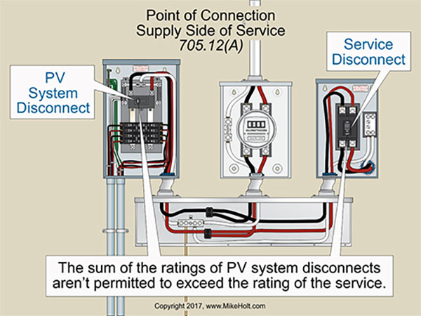
Figure 01
|
|
|
Figure 01
|
For EC&M Magazine
By Mike Holt, NEC® Consultant
Click here to review Part 1, which was sent out last month.
How familiar are you with the Article 705 requirements for PV systems?
Article 705 covers the installation of interconnected generators, solar photovoltaic systems, and fuel cell systems that operate in parallel with a primary source of electricity. Primary sources of electricity would be electric utility power or on-site power source(s). See other important definitions in the Sidebar.
Three quick requirements
- All equipment must be approved for the intended use. Interactive inverters for interconnection service must be listed and/or field-labeled for the use [705.6].
- Only qualified persons may install electrical power production sources operating in parallel with a primary power supply (utility interconnection) [705.8].
- A permanent plaque or directory denoting the location of all electric power disconnecting means must be installed at each service equipment location Exception: Installations with a large number of power production sources can be designated by groups [705.10].
Supply side connection
The system interactive inverter output circuit conductors can be connected on either the supply side or the load side of the service disconnect [705.12].
If you connect the PV system interactive inverter output circuit conductors to the supply side of the service disconnect, follow 230.82(6). Also, the sum of the ratings of all overcurrent protection devices must not exceed the ampere rating of the electric utility service [705.12(A)]. Figure 01
Supply-side conductor connections for PV systems must terminate in an overcurrent protection device that’s within 10 ft of the point of interconnection to the electric utility [705.31].
When determining the number of disconnects per service per 230.71(A), don’t count the PV disconnect(s) connected on the supply side of service equipment. It’s not a service disconnect as defined in Article 100.
Load side connection
If you connect the PV system interactive inverter output circuit conductors to the load side of the service disconnect, PV system circuit conductors must terminate to a dedicated circuit breaker or fusible disconnecting means 705.12(B)(1)].
If you make the PV system connection to a feeder, that portion of the feeder on the load side of the power source output connection must be protected by one of the following [705.12(B)(2)(1)]:
a. The feeder must have an ampacity equal to or greater than the feeder protection device rating plus 125 percent of the PV system rated output circuit current.
b. An overcurrent device on the load side of the PV system connection must not exceed the ampacity of the feeder.
Also:
- Panelboards containing PV ac inverter circuit breakers must be field marked to indicate the presence of all sources of power [705.12(B)(3)].
- Circuit breakers that aren’t marked “Line” and “Load” can be backfed. Fused disconnects are suitable for backfeed applications, unless otherwise marked [705.12(B)(4)]
- Backfed circuit breakers for interactive inverter circuits don’t have to be secured in place by an additional fastener as required by 408.36(D) [705.12(B)(5)]. PV ac inverter circuit breakers don’t have to be fastened in place, because the PV interactive inverter automatically ceases to export ac current from the inverter when the breaker is removed.
Feeder tap sizing for load side connections
Follow the requirements of 240.21. Size the taps as follows:
- 10-foot tap. PV system taps not longer than 10 ft must have an ampacity of at least ten percent of the sum of the feeder protection device plus 125 percent of the PV system rated output circuit current [240.21(B)(1), 705.12(B)(2)(2)].
- 25-foot tap. PV system taps not longer than 25 ft must have an ampacity of at least thirty-three percent of the sum of the feeder protection device plus 125 percent of the PV system rated output circuit current [240.21(B)(2)].
In no case can the ampacity of any tap be less than the rating of the terminating overcurrent protection device, per 240.21(B)(1).
Busbar protection for load side connections
Determine busbar ampacity by applying one of these four rules [705.12(B)(2)(3)]:
- One-Hundred and Twenty-Five Percent Rule. The busbar must have an ampacity of at least 125 percent of the PV system output circuit current rating, plus the rating of the overcurrent device protecting the busbar [705.12(B)(2)(3)(a)].
- One-Hundred and Twenty Percent Rule. Where the PV system overcurrent protection device is located at the opposite end of the feeder conductor termination, the sum of 125 percent of the PV system output circuit current rating, plus the rating of the overcurrent device protecting the busbar can’t exceed 120 percent of the busbar ampacity. A permanent warning label, complying with 110.21(B), must be applied to the distribution equipment adjacent to the back-fed breaker [705.12(B)(2)(3)(b)].
- One-Hundred Percent Rule. The sum of the ampere ratings of all overcurrent devices on the busbar does not exceed the ampacity of the busbar. A permanent warning label, complying with 110.21(B), must be applied to the distribution equipment [705.12(B)(2)(3)(c)].
- Center-Fed Panelboard Rule. The sum of 125 percent of the PV system output circuit current rating, plus the rating of the overcurrent device protecting the busbar can't exceed 120 percent of the busbar ampacity [705.12(B)(2)(3)(d)].
Power loss
Upon loss of the electric utility power, the inverter ac output circuit must automatically disconnect from the electric utility power source and not reconnect until the electric utility power source has been restored [705.40].
Ex: A listed interactive inverter is permitted to automatically cease exporting power upon loss of electric utility power and to resume exporting power once the electric utility power source has been restored.
Unbalanced Interconnections
Single-phase inverters connected to a three-phase electric utility power source must not increase electric utility unbalanced system voltage at the service to more than three percent [705.100(A)].
An example of an unbalanced interconnection would be connecting two single-phase inverters to a three-phase system.
ANSI C84.1 recommends that “electric supply systems should be designed to limit the maximum voltage unbalance to three percent when measured at the electric-utility revenue meter under no-load conditions.” Improperly connecting single-phase inverters to a three-phase system can result in a significant increase in unbalanced system voltage. Three-phase motors will run hotter using unbalanced voltage because the unbalanced magnetic fields created by the windings work against each other.
The formula to determine maximum unbalanced voltage is:
Maximum Unbalanced Voltage = 100 x Maximum Deviation from Average Voltage/Average Voltage.
Existing installation example: If we connect two single-phase PV systems to lines B - C and this causes the B - C voltage to increase from 200V to 202V because of a decrease in loading, the maximum unbalanced system voltage for the following line voltages: A - B 206V, B - C 201V, and A - C 204V will be _____ percent.
Solution:
Average Voltage = (206V + 202V + 204V)/3 lines = 204V
Maximum Deviation from Average = 206V - 204 = 2V
Maximum Unbalanced Voltage = 2V/204V x 100 = 1%
Answer: 1 percent
Unbalanced system voltage two inverters example: If we connect two single-phase PV systems to lines B - C and this results in B - C voltage to rise from 200V to 201V because of a decrease in loading, the maximum unbalanced system voltage for the following line voltages: A - B 206V, B - C 201V, and A - C 204V will be _____ percent.
Solution:
Average Voltage = (206V + 201V + 204V)/3 lines = 203.66V
Maximum Deviation from Average = 206V - 203.66V = 2.34V
Maximum Unbalanced Voltage = 2.34V/203.66V x 100 = 1.15%
Answer: 1.15 percent
Avoiding interconnection errors
Your first decision is whether the point of connection will be on the supply side or load side of the service disconnect. Either way, you have many requirements to meet. The supply side ones are mostly in Article 230.
One way to help ensure code compliance is to put those requirements into separate checklists for design and installation. But only after you’ve taken the time to understand them.
Sidebar: Definitions [705.2]
Interactive inverter output circuit. The conductors between the PV interactive inverter and the service equipment or another electric power production source, such as a utility, for an electrical production and distribution network.
Multimode inverter. Equipment having the capabilities of both the inverter and the stand-alone inverter.
Power production equipment. The generating source, and all distribution equipment associated with it, that generates electricity from a source other than a utility supplied service. Note: Examples of power production equipment include such items as generators, solar photovoltaic systems, and fuel cell systems.
Qualified person. One with the knowledge related to construction and operation of PV equipment and installations; along with safety training to recognize and avoid hazards to persons and property [Article 100].
|