|
For EC&M Magazine
By Mike Holt, NEC® Consultant
Here's the follow-up to yesterday's newsletter.
This includes the answers to the questions sent, so you can see how you did.

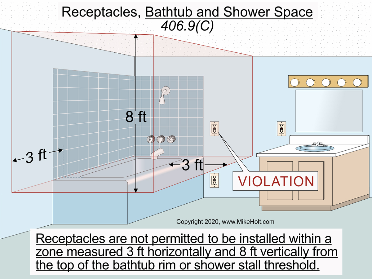
Figure 01
|
|
|
Figure 01
|
For EC&M Magazine
By Mike Holt, NEC® Consultant
Here's the follow-up to yesterday's newsletter.
This includes the answers to the questions sent, so you can see how you did.
Note: The answers to these questions are based on the 2020 NEC.
Underlined text indicates a change for the 2020 NEC.
Q1. What is the Code requirement for an Emergency Disconnect for one and two family dwellings?
A1. 230.85 Emergency Disconnects
For one- and two-family dwelling units, all service conductors must terminate in a disconnecting means having a short-circuit current rating equal to or greater than the available fault current and installed in a readily accessible outdoor location. If more than one disconnect is provided, they must be grouped. Each disconnect must be one of the following:
(1) Service disconnects marked: EMERGENCY DISCONNECT, SERVICE DISCONNECT
(2) Meter disconnects installed in accordance with 230.82(3) must be marked: EMERGENCY DISCONNECT, METER DISCONNECT, NOT SERVICE EQUIPMENT
(3) Other listed disconnect switches or circuit breakers on the load side of the meter and supply side of each service disconnect marked: EMERGENCY DISCONNECT, NOT SERVICE EQUIPMENT
Markings must be permanently affixed and have sufficient durability to withstand the environment involved in accordance with 110.21(B).
Author’s Comment:
►Option (1) permits an outside service disconnect to be both the service disconnect and the emergency disconnect. In some areas it is already common to locate the service disconnect on the exterior and the only thing that changes in those cases is the new marking that is required.
►Option (2) permits a meter disconnect to serve as the required emergency disconnect. This is useful where the utility has required the installation of a meter disconnect. The meter disconnect must be installed in accordance with the requirements of 230.83(3) and must be marked.
►Option (3) provides for the installation of other listed disconnect switches or circuit breakers that are suitable for use as service disconnects and are marked as such.
Q2. What are the NEC rules for the location of receptacles in damp or wet locations of bathrooms?
A2. Receptacles in Damp or Wet Locations 406.9
(C) Bathtub and Shower Space. Receptacles are not permitted to be installed within a zone measured 3 ft horizontally and 8 ft vertically from the top of the bathtub rim or shower stall threshold. The zone is all-encompassing and includes the space directly over the tub or shower stall.Figure 01
Ex to (C): In bathrooms with less than the required zone, a receptacle is permitted on the furthest wall opposite the bathtub rim or shower stall threshold.
Q3. What are the NEC rules for the location of luminaires in bathtub and shower areas?
A3. 410.10 Luminaires in Specific Locations
(D) Bathtub and Shower Areas. A luminaire installed in a bathtub or shower area must meet all of the following requirements:
(1) No part of chain-, cable-, or cord-suspended luminaires, track luminaires, or ceiling paddle fans can be located within 3 ft horizontally and 8 ft vertically from the top of the bathtub rim or shower stall threshold.
(2) Luminaires located within the outside dimensions of a bathtub or shower to a height of 8 ft from the top of the bathtub rim or shower threshold must be marked for damp locations or marked suitable for wet locations. Where subject to shower spray, the luminaires must be marked suitable for wet locations.
Author’s Comment:
►The previous Code language actually required that the luminaire be marked “wet locations where subject to shower spray.” There is no such marking on any luminaire.
Q4. Where does the Code require tamper-resistant receptacles?
A4. 406.12 Tamper-Resistant Receptacles
Nonlocking-type 15A and 20A receptacles in the following areas must be tamper resistant “TR”:
Author’s Comment:
►Inserting an object into one slot of a tamper-resistant receptacle does not open the internal shutter mechanism. Simultaneous pressure applied to the polarized slots is required to insert the plug.
(1) Dwelling units, including attached and detached garages and accessory buildings, and common areas of multifamily dwellings specified in 210.52.
(2) Hotel and motel guest rooms and guest suites, and their common areas.
(3) Childcare facilities.
Author’s Comment:
►A childcare facility is a building or portions thereof used for educational, supervision, or personal care services for five or more children seven years in age or less [406.2].
(4) Preschools and education facilities.
Author’s Comment:
►In response to a Public Comment to restore the word “elementary” to this section, the Code-Making Panel (CMP) said: “Elementary was removed in the first revision due to the ambiguity as to what age group of children will occupy the space. High school and college facilities also warrant this protection.”
(5) Business offices, corridors, waiting rooms and the like in clinics, medical and dental offices, and outpatient facilities.
(6) Places of awaiting transportation, gymnasiums, skating rinks, and auditoriums.
(7) Dormitory units.
(8) Assisted living facilities.
Ex: Receptacles in the following locations are not required to be tamper resistant:
(1) Receptacles located more than 5½ ft above the floor.
(2) Receptacles that are part of a luminaire or appliance.
(3) A receptacle located within dedicated space for an appliance that in normal use is not easily moved.
(4) Where nongrounding receptacles are installed as permitted in 406.4(D)(2)(a)8.
Q5. What is the NEC rule for tightening torque of electrical terminal connections?
A5. 110.14 Conductor Termination and Splicing
(D) Terminal Connection Torque. Tightening torque values for terminal connections must be as indicated on equipment or installation instructions. An approved means, (torque tool), must be used to achieve the indicated torque value.
Author’s Comment:
►Conductors must terminate in devices that have been properly tightened in accordance with the manufacturer’s torque specifications included with equipment instructions. Failure to torque terminals properly can result in excessive heating of terminals or splicing devices due to a loose connection. A loose connection can also lead to arcing which increases the heating effect and may also lead to a short circuit or ground fault. Any of these can result in a fire or other failure, including an arc flash event. In addition, this is a violation of 110.3(B), which requires all equipment to be installed in accordance with listing or labeling instructions.
Instructional Note 1: Examples of approved means of achieving the indicated torque values include torque tools or devices such as shear bolts or breakaway-style devices with visual indicators that demonstrate the proper torque has been applied.
Instructional Note 2: The equipment manufacturer can be contacted if numeric torque values are not indicated on the equipment or if the installation instructions are not available. Annex I of UL Standard 486A-486B, Standard for Safety-Wire Connectors, provides torque values in the absence of manufacturer’s recommendations.
Instructional Note 3: Additional information for torqueing threaded connections and terminations can be found in Section 8.11 of NFPA 70B, Recommended Practice for Electrical Equipment Maintenance.
Author’s Comment:
►Connections are arguably one of the most common points of electrical failure and properly making those connections properly is critical in preventing connection failures. Either too tight or too loose can result in connection failures and it is difficult to manually find the optimal intersect of mechanical strength and the most desirable performance.
►There is still no guidance as to how often a torqueing tool must be calibrated or who is to do so. The revised rule just requires an approved means to achieve the required torque value. This approved means could be a torque tool or a fastener with some type of torque indicator. One such indicator is a double head bolt found on some electrical equipment, where the outer head snaps off at the required torque.
►This rule is still difficult from an enforcement point of view. You may need to try to verify what the authority having jurisdiction (AHJ) requires. Some may want to be present to watch the torqueing of the connection, others may just want to see the tool, and some want to see a “sign off” sheet with the equipment location, the torque value, the date, and the name of the person who torqued the connection. New Informational Notes provide some additional guidance. (See Notes: 1, 2, and 3.)
|