|
For EC&M Magazine
By Mike Holt, NEC® Consultant
Note: This article is based on the 2020 NEC.
Requirements for boatyards and marinas are tighter because of increased attention to electrical shock drowning incidents.
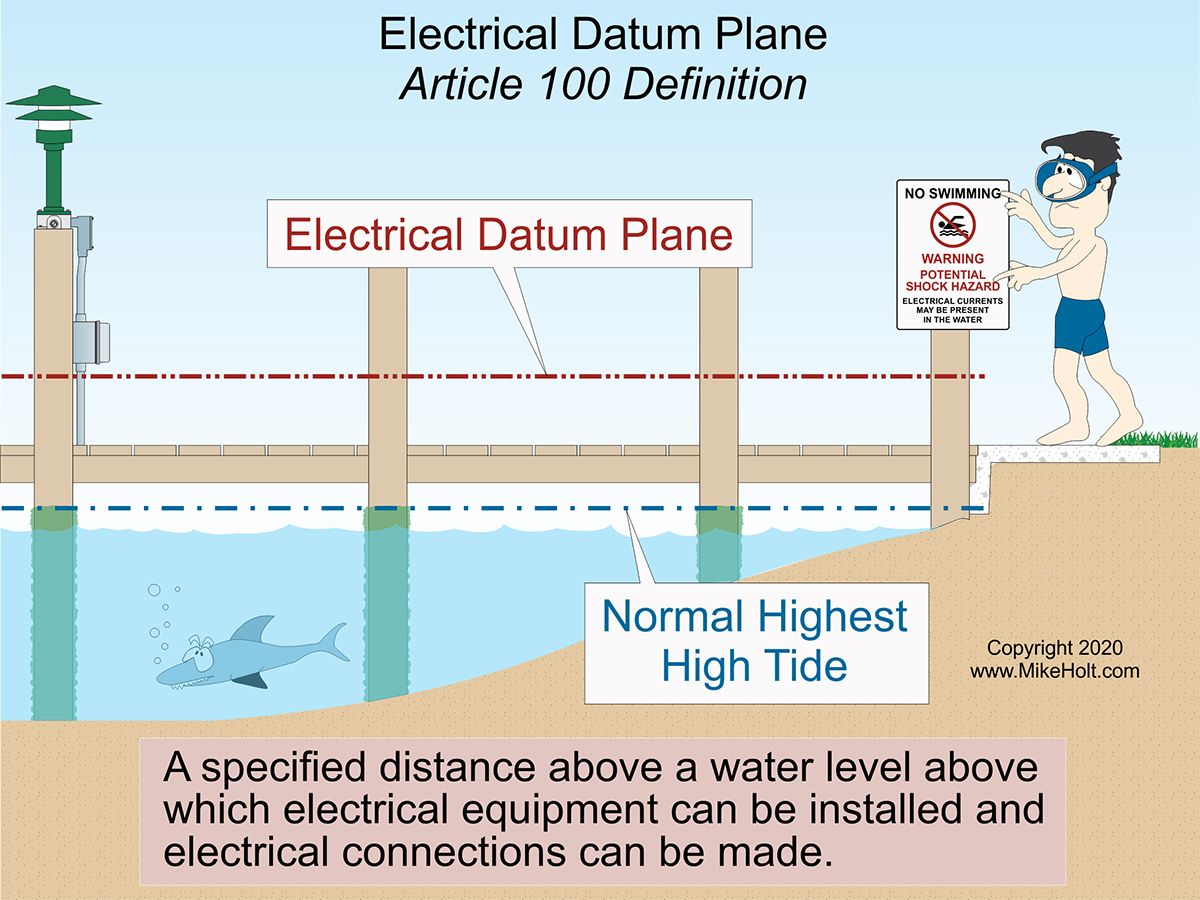
Figure 01
|
|
|
Figure 01
|
For EC&M Magazine
By Mike Holt, NEC® Consultant
Note: This article is based on the 2020 NEC.
Requirements for boatyards and marinas are tighter because of increased attention to electrical shock drowning incidents.
Article 555 begins with the concept of the electrical datum plane. This plane is a specified distance above a water level. Above the electrical datum plane, you can install electrical equipment and make electrical connections. Article 100 has four definitions describing various datum plane conditions. Figure 01
The electrical datum plane:
- For floating piers and boat landing stages is a horizontal plane 30 in. above the water level at the floating pier and a minimum of 12 in. above the level of the deck [555.3(A)].
- In land areas subject to tidal fluctuation is a horizontal plane 2 ft above the highest tide level for the area occurring under normal circumstances, based on the highest high tide [555.3(B)].
- In land areas not subject to tidal fluctuation is a horizontal plane 2 ft above the highest water level for the area occurring under normal circumstances [555.3(C)].
Power distribution
The service equipment for a floating building, dock, or marina must be on land adjacent to the structure served, but not on or in the structure itself [555.4].
Pier power distribution systems must not exceed 250V phase to phase. Pier power distribution systems, where qualified personnel service the equipment under engineering supervision, can exceed 250V but must not exceed 600V [555.5].
When calculating service and/or feeder ampacities, you can apply the demand factors shown in Table 555.6 [555.6].
Transformers and enclosures must be identified for wet locations. The bottom of a transformer enclosure cannot be below the electrical datum plane [555.7(A)].
Boat hoists
GFCI protection is required for a boat hoist not exceeding 240V installed at dwelling unit docking facilities [555.9]. This section was previously covered in 210.8(C) but is in Article 555 because it now covers dwelling unit docking facilities.
Signage
A permanent safety sign is required. It must give notice of electrical shock hazard risks to persons using or swimming near a docking facility, boatyard, or marina [555.10]. The safety sign must meet these requirements:
(1) The sign must warn of the hazards using effective words, colors, or symbols (or a combination) per 110.21(B)(1) and be of sufficient durability to withstand the environment.
(2) The signs must be clearly visible from all approaches to a marina or boatyard facility.
(3) The sign must state:
WARNING—POTENTIAL SHOCK HAZARD—ELECTRICAL CURRENTS MAY BE PRESENT IN THE WATER.
That’s at a minimum. There is nothing preventing you from posting additional signage.
Hazardous locations
Electrical wiring and equipment located at or serving motor fuel dispensing locations must comply with Article 514 plus the requirements of this article [555.11].
Electrical wiring and equipment at marine craft repair facilities containing flammable or combustible liquids or gases must comply with Article 511 plus the requirements of this article [555.12].
Important rules in Article 511 to consider include:
- 511.3—Classification of Hazardous Areas
- 511.4—Wiring and Equipment in Hazardous (Classified) Locations
- 511.7—Wiring and Equipment Above Hazardous (Classified) Locations
- 511.9—Explosionproof Seals
- 511.12—GFCI-Protected Receptacles
Bonding
Metal parts in contact with the water, metal piping, and noncurrent-carrying metal parts likely to become energized must be connected to the grounding bus in the panelboard using a solid copper conductor that is insulated, covered, or bare and at least 8 AWG [555.13]. Make the connections per 250.8.
Electrical connections
Electrical connections must be at least 12 in. above the deck of a:
- Floating pier [555.30(A)].
- Fixed pier and not below the electrical datum plane [555.30(B)].
Replacement electrical connections for a floating pier must be at least 12 in. above its deck. Conductor splices above the waterline but below the electrical datum plane for floating piers must be within junction boxes identified for wet locations, using sealed wire connector systems listed and identified for submersion [555.30(C)].
Receptacles
Receptacles must be mounted at least 12 in. above the deck surface, and not below the electrical datum plane on a fixed pier [555.33].
Receptacles intended to supply shore power to boats must be part of a listed marina power outlet enclosure. Install them in listed enclosures protected from the weather or in listed weatherproof enclosures [555.33(A)(1)].
Receptacles that provide shore power for boats must be rated at least 30A; they must be of the pin and sleeve type if rated 60A or higher [555.33(A)(4)].
Receptacles in other locations must be GFCI protected per 210.8 [555.33(B)(1)]. Replacement receptacles must comply with 555.33 [555.33(C)].
Wiring methods
You can use any Chapter 3 wiring method identified for wet locations [555.34(A)(1)].
You can use sunlight resistant, extra-hard usage portable power cables listed for wet locations. But only if they have an outer jacket resistant to temperature extremes (not less than 167°F), oil, gasoline, ozone, abrasion, acids, and chemicals [555.34(A)(2)]. And you can use them only:
- As permanent wiring on the underside of piers (floating or fixed).
- Where flexibility is necessary (as on piers composed of floating sections).
Temporary wiring, except as permitted by Article 590, must not be used to supply power to boats [555.34(A)(3)].
You can use multiple feeders and branch circuits outdoors [555.34(B)(2)]. Clearances for overhead branch-circuit and feeder wiring in locations of the boatyard other than those described in 555.34(B)(1) must be at least 18 ft above grade. Only Part I of Article 225 applies to marina installations.
Portable power cables [555.34(B)(3)(a)]
Portable power cables permitted by 555.13(A)(2) must be:
(1) Properly supported.
(2) Located on the underside of the pier.
(3) Securely fastened by nonmetallic clips to structural members other than the deck planking.
(4) Not be subject to physical damage.
(5) Protected against chafing by a permanently installed oversized sleeve of nonmetallic material when cables pass through structural members.
Where portable power cables are used, there must be a junction box of corrosion-resistant construction with permanently installed terminal blocks on each pier section to which the feeders are connected [555.34(B)(3)(b)].
You can use a listed marina power outlet employing terminal blocks/bars in lieu of a junction box. Metal junction boxes and covers, and metal screws and parts that are exposed externally to the boxes, must be of corrosion-resistant materials or protected by material resistant to corrosion.
Protect wiring above the decks of piers and landing stages by using rigid metal conduit, reinforced thermosetting resin conduit (RTRC) listed for aboveground use, or rigid polyvinyl chloride (PVC) conduit suitable for the location.
Ground fault protection
For other than floating buildings, provide ground-fault protection for docking facilities as follows [555.35(A)]:
(1) GFPE Protection. Receptacles installed per 555.33(A) can have individual GFPEs set to open at currents not exceeding 30 mA.
(2) GFCI Protection. All 15A and 20A, 125V receptacles for other than shore power must be protected per 555.33(B)(1) and (B)(2).
(3) Feeder and Branch-Circuit Conductors with GFPE. Feeder and branch-circuit conductors installed on docking facilities must be provided with GFPEs set to open at currents not exceeding 100 mA. Coordination with the feeder GFPE overcurrent protective device is permitted.
Ex to (3): Transformer secondary conductors of a separately derived system that do not exceed 10 ft and are in a raceway can be installed without ground-fault protection. This exception also applies to the supply terminals of the equipment supplied by the transformer secondary conductors.
Leakage current
Where more than three receptacles supply shore power to boats, a leakage current measurement device must be available. It must be used to determine leakage current from each boat that will utilize shore power [555.35(B)].
Boat receptacle disconnect
A disconnect must isolate each boat from its shore power receptacle [555.36]. A circuit breaker or switch must be used as the required shore power receptacle disconnect and it must be identified as to which receptacle it controls.
The disconnect for shore power receptacles must be readily accessible and not more than 30 in. from the receptacle it controls. Circuit breakers or switches in marina power outlets can be used for the shore power receptacle disconnect [555.36(B)].
Equipment grounding conductor
The following must be connected to an equipment grounding conductor (EGC) run with the circuit conductors in the same raceway, cable, or trench [555.37]:
(1) Metal boxes, metal cabinets, and all other metal enclosures.
(2) Metal frames of utilization equipment.
(3) Grounding terminals of grounding-type receptacles.
The EGC must be an insulated conductor with a continuous outer finish that is either green or green with one or more yellow stripes. Size it per 250.122, but not smaller than 12 AWG.
Safe power
To safely provide power to a marina, boatyard, or docking facility, you must allow for variations in water level between the point of use and the electric power source. Understanding and respecting the electrical datum plane is vital to doing that correctly.
For more information visit our webpage www.MikeHolt.com/marinas

|