|
By Mike Holt
NEC® Consultant for EC&M Magazine
Note: This article is based on the 2020 NEC.
Grounding and bonding serve different functions, use different methods, and have different requirements.
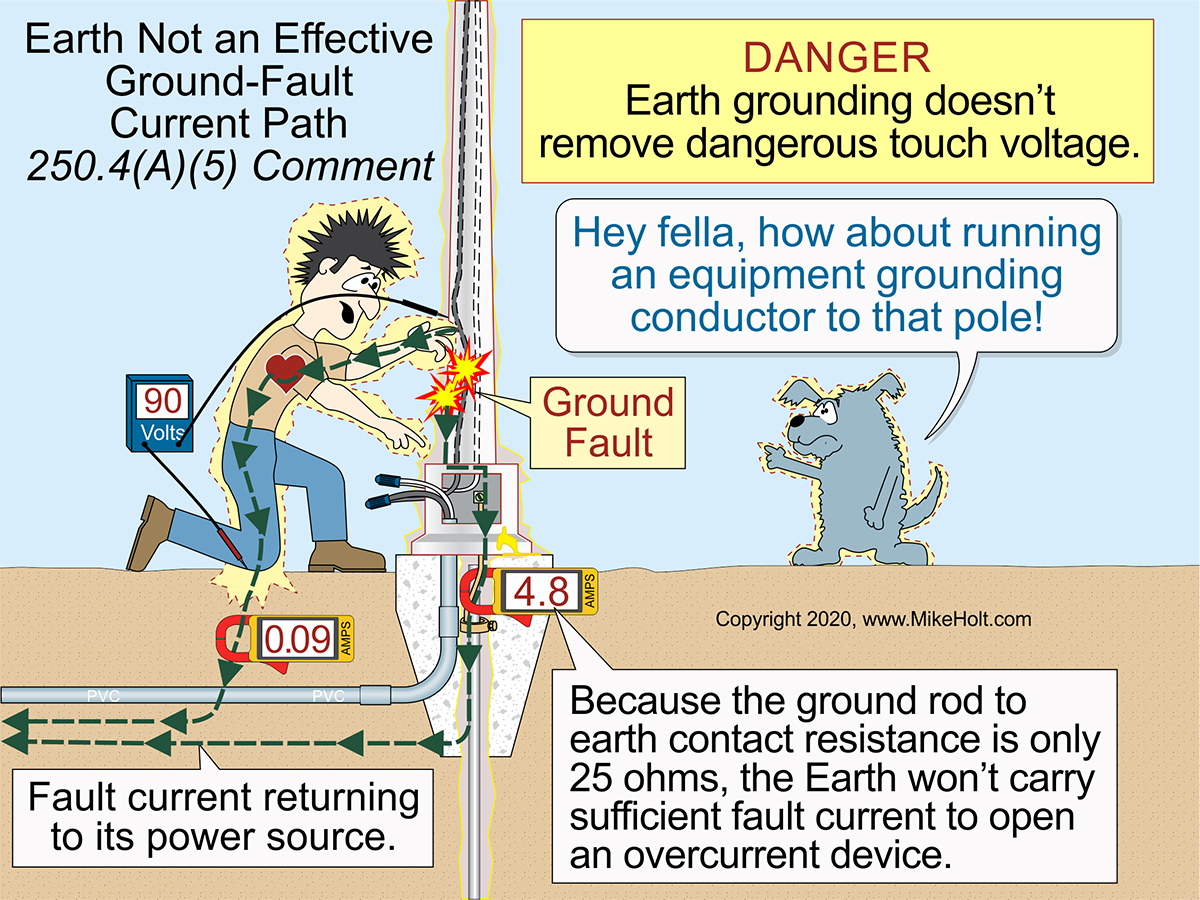
Figure 01
|
|
|
Figure 01
|
By Mike Holt
NEC® Consultant for EC&M Magazine
Note: This article is based on the 2020 NEC.
Grounding and bonding serve different functions, use different methods, and have different requirements.
Article 250 provides requirements for the grounding and bonding of electrical installations. It covers two different concepts:
1. “Grounding” which is the connection to the earth. The grounding requirements provide a path to the earth to reduce overvoltage from lightning strikes, line surges, or unintentional contact by higher-voltage lines [250.4(A)(1)].
Failure to ground metal parts to earth can result in millions of volts induced on those metal parts. This energy seeks a way to the earth within the building, taking whatever paths are available (not just “the one with least resistance”, see Kirchhoff’s Law of Parallel Circuits). This can easily result in a fire and/or electric shock either by direct contact or from a flashover.
2. “Bonding” which is mechanically connecting electrically conductive components to ensure electrical conductivity between metal parts [Article 100]. The bonding requirements establish a low-impedance fault current path back to the source of the electrical supply so overcurrent protective devices (OCPDs) operate if there’s a ground fault [250.4(A)(3)].
These two systems overlap, but each serves a different purpose. You need them in both solidly grounded systems [250.4(A)] and ungrounded systems [250.4(B)].
Effective ground-fault current path
An “effective ground-fault current path” [Article 100 and 250.4(A)(5)] is:
- An intentionally constructed low-impedance conductive path.
- Designed to carry fault current from the point of a ground fault to the source.
- Needed for opening the circuit OCPD.
- Capable of safely carrying the maximum ground-fault current likely to be imposed on it from any point on the wiring system where a ground fault may occur to the electrical supply source.
- Not the earth.
- Is of a type recognized in 250.118 and must be installed with all circuits.
Also, it has sufficiently low impedance to the source so fault current will quickly rise to a level that will open the circuit OCPD. The time it takes for an OCPD to open depends on the magnitude of the fault current. A higher fault current value means a shorter clearing time for the OCPD. For example, a 20A OCPD with an overload of 40A (two times the 20A rating) takes 25 to 150 seconds to open. The same device at 100A (five times the 20A rating) trips in 5 to 20 seconds.
During a ground fault, earth grounding does not remove dangerous touch voltage. Because the contact resistance of a grounding electrode (like a ground rod) to the earth is so high, very little fault current returns to the power supply. As a result, the circuit OCPD will not open, and all metal parts associated with the electrical installation, metal piping, and structural building steel will become (and remain) energized. Figure 01
Electricity will take all paths presented to it in inverse proportion to the impedances. A low-impedance path takes (almost) all the undesired current. Draw a circuit with two 10K ohm resistors in parallel. Calculate the current flow. Now put a 1 ohm resistor in parallel with those and recalculate. What did you learn about low impedance paths, such as the effective ground-fault current path, by doing this?
Solidly grounded systems
System grounding reduces fire risk. It also reduces voltage stress on electrical insulation, thereby extending insulation life for motors, transformers, and conductors.
Solidly grounded electrical power systems must connect to the earth (grounded) in a manner that limits the voltage induced on the conductors by lightning strikes, etc. If the source is a transformer, grounding stabilizes the secondary conductor’s voltage to ground during normal operation [250.4(A)(1)].
To limit imposed voltage, grounding electrode conductors should not be any longer than necessary or have unnecessary bends or loops [250.4(A)(1) Note 1].
Metal parts of electrical equipment must be connected to each other and to the earth to reduce the voltage (to ground) on the metal parts from indirect lightning strikes [250.4(A)(2)].
Metal parts of electrical raceways, cables, enclosures, and equipment must be connected together and to the supply system in a manner that establishes an effective ground-fault current path [250.4(A)(3)].
Electrically conductive materials that are likely to become energized, such as metal water piping systems, metal sprinkler piping, metal gas piping, and exposed structural steel members must be connected (bonded) to the supply source via an effective ground-fault current path. [250.4(A)(4)].
Metal parts of electrical raceways, cables, enclosures, or equipment must be bonded together and to the supply source in a manner that creates a low-impedance path [250.4(A)(5)].
Ungrounded systems
An ungrounded system is “a power-supply system not connected to earth (ground)” [100]. An example is in the secondary winding of a transformer where there is no connection between the system winding and earth (ground) or to a conductive body that extends the earth (ground) connection.
Ungrounded systems must still be grounded. Do it per 250.4(B)(1) through 250.4(B)(4). The requirements are similar to those for solidly grounded systems. In fact:
- 250.4(B)(1) repeats 250.4(A)(2).
- 250.4(B)(2) repeats 250.4(A)(3).
- 250.4(B)(3) repeats 250.4(A)(4).
- 250.4(B)(4) repeats 250.4(A)(5).
And the requirements for the effective ground-fault path are the same. So where is the difference?
A solidly grounded system connects to the earth, for example a delta-wye transformer is connected via grounding conductor at the “Y” point in the transformer drawing. From a normal operating perspective, this merely stabilizes the voltage on the secondary. You could have a relatively puny connection to ground and it would still work.
But what if there is an induced voltage in the system? That’s where 250.4(A)(1) comes in. It requires this ground connection to be sufficient for handling the abnormal induced voltage. Ungrounded systems don’t have this connection, so this requirement does not apply to them. This connection at the source is what differentiates solidly grounded systems from ungrounded systems.
Objectionable neutral current
Objectionable neutral current occurs because of improper neutral‑to‑case connections or wiring errors that violate 250.142(B). Objectionable neutral current on metal parts can cause electric shock, fires, and improper operation of electronic equipment and OCPDs such as GFPEs, GFCIs, and AFCIs.
Electrical systems and equipment must be installed in a manner that prevents neutral current or circuit current from flowing on metal parts (objectionable current) [250.6(A)].
Objectionable neutral current will flow on metal parts if the neutral conductor is connected to the circuit equipment grounding conductor at both the transformer and any other location on the load side of the system bonding jumper.
Objectionable neutral current will flow on the equipment grounding conductor if the circuit equipment grounding conductor is used as a neutral conductor, such as where:
- A 230V time-clock motor is replaced with a 115V time-clock motor, and the circuit equipment grounding conductor is used for neutral return current.
- A 115V water filter is wired to a 240V well-pump motor circuit, and the circuit equipment grounding conductor is used for neutral return current.
- The circuit equipment grounding conductor is used for neutral return current.
Objectionable neutral current will flow on metal parts and on the equipment grounding conductor(s) if:
- The neutral conductor is connected to the metal case of a panelboard on the load side of the service disconnect.
- A generator is connected to a transfer switch with a solidly connected neutral, and a neutral-to-case connection is made at the generator.
- The neutral conductor is connected to the metal case of a disconnect that is not part of the service disconnect.
- The neutral conductor from one system is used as the neutral conductor for a different system.
Grounding and bonding connectors
Equipment grounding conductors, grounding electrode conductors, and bonding jumpers must be connected by one or more of these methods [250.8(A)]:
(1) Listed pressure connectors
(2) Terminal bars
(3) Pressure connectors listed for grounding and bonding
(4) Exothermic welding
(5) Machine screws that engage at least two threads or are secured with a nut
(6) Self-tapping machine screws that engage at least two threads in the enclosure
(7) Connections that are part of a listed assembly
(8) Other listed means
Beyond general requirements
To avoid confusion, remember that grounding involves connecting to the dirt but bonding involves providing a metallic path. Drawing out the circuit is a good way to get a clear picture of where undesired current is flowing, but only if you show grounding as a big resistor and bonding as a small one.
|