Myth No. 1 – Grounding and Ideal
This is the first installment of a new series we’re developing to uncover industry myths.
Pathway to ground: Pathway to Improve Safety and Power Quality
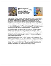 IDEAL Industries, T&M Division
http://www.idealindustries.com/pdf/tm/Pathway%20to%20ground.pdf
Mike Holt’s Comment: The following text by Ideal is typical in what we see written on the topic of Grounding in our industry with lots of false statements.
Ideal: When the topic of power grounds comes up, the focus tends to be on the earth ground system itself, whether a single ground rod, mat, or grid system. While a low effective resistance is very important, the ground conductor and the terminations on that conductor will often be overlooked. A fault current has to pass through every connection on a ground conductor before it can reach the earth to be safely carried away.
Mike Holt: Fault current is not trying to reach the earth, it’s trying to get to the source.
Ideal: Testing of the effective resistance of a ground is important, but a good testing program must include the ground conductors and it’s connections and splices. The electrical ground system ultimately includes the grounded device itself, and the entire pathway back to the earth ground.
Ideal: The impedance of the ground conductor can be seen as the pathway that a faulted current will have to take to reach the earth ground system.
Mike Holt: Fault current is not trying to get to the earth, it’s trying to get to the source.
Ideal: When insulation fails, a short circuit occurs. Protective devices like fuses or breakers open to stop the fault current, but before these devices can act, the ground conductor must carry the fault enough to become a lower pathway to ground could suffer the consequence.
Mike Holt: This makes no sense.
Ideal: This high resistance bond can be a source of power quality problems as well.
Mike Holt: Is it ground or bond?
Ideal: Modern digital electronics work at 5-volt levels or less, switching, communicating and controlling our automated industrial processes. Imagine the problems fault currents cause when they produce voltage on the ground side of solid-state circuits. This common problem can be resolved completely by providing low resistance pathways for fault current to follow to earth ground.
Mike Holt: Grounding (a connection to the earth) does not reduce voltage on metal parts from a ground fault.
Ideal: Another related power quality issue is stray voltage. Very commonly caused by connecting the ground and neutral conductor in a sub-panel, stray voltage can energize all exposed metal and building steel. Stray voltage in dairy farms causes cows to eventually stop giving milk, and in hospitals will cause many problems with high tech diagnostic equipment, and patient connected equipment.
Mike Holt: I’m not sure what this has to do with the article on Grounding, because grounding does not reduce Stray Voltage.
Ideal: In our modern electrical environment, non-linear loads cause high neutral currents. The neutral conductor can carry substantial current back to the earth ground system.
Mike Holt: The grounding conductor (conductor to the earth) plays no role in nonlinear loads, and neutral current is not trying to get to the earth.
Ideal: The ground conductor is not considered an electrical conductor, and is present to provide a low resistance pathway for fault current.
Mike Holt: Grounding to the earth is not intended to provide a low resistive path for fault current.
Ideal: The neutral must be carried back to the service entrance, and can only be bonded to the ground conductor at the main neutral buss, where a large copper conductor carries all the return and faulted current back to the earth.
Mike Holt: Ground fault current is not attempting to return to the earth.
Ideal: Sometimes through error or ignorance, the neutral and ground are connected upstream from the service entrance. This is called a false, or bootleg ground. If the neutral and ground are connected anywhere else in the building, all grounded metal becomes part of the neutral conductor, constantly energized and creating various voltage potentials on electronic equipment. This causes many nuisance problems with automated equipment and computers, but can also create a hazardous and expensive electrical environment.
Mike Holt: I don’t understand the comment about expensive electrical environment.
Ideal: The solution to these problems is to include complete ground pathway testing as part of the standard procedure in your facility, and to choose test equipment which will help you locate and identify high resistance ground paths, and locate and eliminate bootleg grounds.


 Send to a Friend