|
 Keeping up with the requirements of the Code should be the goal of everyone involved in electrical safety. Here is the 6th newsletter with what I feel is an important rule in the 2017 NEC®, complete with graphics and a video. I encourage you to use it as a training resource for your organization, and share it with your colleagues. Keeping up with the requirements of the Code should be the goal of everyone involved in electrical safety. Here is the 6th newsletter with what I feel is an important rule in the 2017 NEC®, complete with graphics and a video. I encourage you to use it as a training resource for your organization, and share it with your colleagues.

The content below is extracted from Mike Holt's Understanding the 2017 National Electrical Code®, Volume 1.
Any underlined text denotes a change to the Code for the 2017 NEC.
|
314.28 Sizing Conductors 4 AWG and Larger |
Boxes containing conductors 4 AWG and larger that are required to be insulated must be sized so the conductor insulation won't be damaged.
| Author's Comment: |
- The requirements for sizing boxes containing conductors 6 AWG and smaller are contained in 314.16.
- If conductors 4 AWG and larger enter a box or other enclosure, a fitting that provides a smooth, rounded, insulating surface, such as a bushing or adapter, is required to protect the conductors from abrasion during and after installation [300.4(G)].
|
(A) Minimum Size. For raceways containing conductors 4 AWG and larger, the minimum dimensions of boxes must comply with the following:
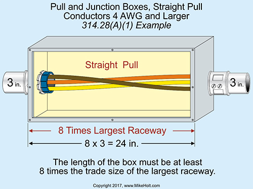
(1) Straight Pulls. The minimum distance from where the conductors enter the box to the opposite wall isn't permitted to be less than eight times the trade size of the largest raceway. ▶Figure 314“54
(2) Angle Pulls, U Pulls, or Splices.
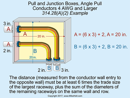
Angle Pulls. The distance from the raceway entry of the box to the opposite
wall isn't permitted to be less than six times the trade size of the
largest raceway, plus the sum of the trade sizes of the remaining raceways
on the same wall and row. ▶Figure 314“55
|
|
Figure 314“54 |
|
|
Figure 314“55 |
|
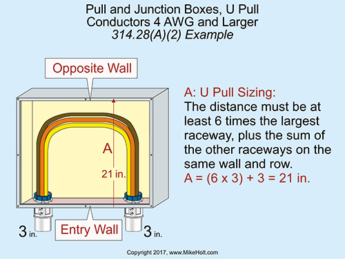
U Pulls. When a conductor enters and leaves from the same wall of the
box, the distance from where the raceways enter to the opposite wall
isn't permitted to be less than six times the trade size of the largest
raceway, plus the sum of the trade sizes of the remaining raceways on
the same wall and row. ▶Figure 314“56
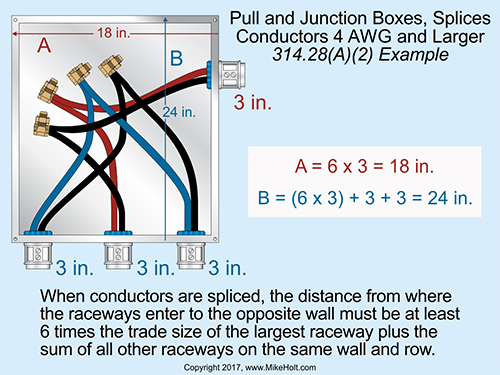
Splices. When conductors are spliced, the distance from where the raceways
enter to the opposite wall isn't permitted to be less than six times
the trade size of the largest raceway, plus the sum of the trade sizes
of the remaining raceways on the same wall and row. the trade sizes of the remaining raceways on
the same wall and row. ▶Figure 314“57
|
|
Figure 314“56 |
|
|
Figure 314“57 |
|
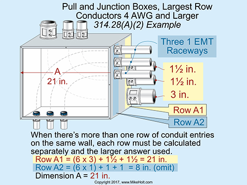
Rows. If there are multiple rows of raceway entries, each row is calculated individually and the row with the largest distance must be used. ▶Figure 314“58
|
|
Figure 314“58 |
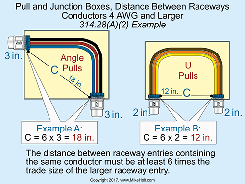
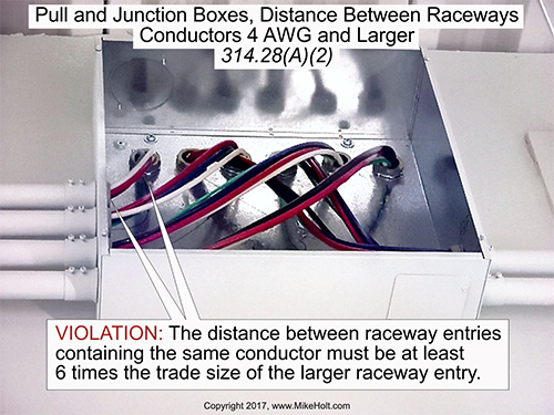
Distance Between Raceways. The distance between raceways enclosing the same conductor isn't permitted to be less than six times the trade size of the largest raceway, measured from the raceways' nearest edge-to-nearest edge. ▶Figure 314“59 and ▶Figure 314“60
|
|
Figure 314“59 |
|
|
Figure 314“60 |
|
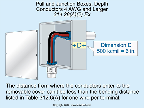
Ex: When conductors enter an enclosure with a removable cover, the distance from where the conductors enter to the removable cover isn't permitted to be less than the bending distance as listed in Table 312.6(A) for one conductor per terminal. ▶Figure 314“61
(B) Conductors in Pull or Junction Boxes. Pull boxes or junction boxes with any dimension over 6 ft must have all conductors cabled or racked in an approved manner.
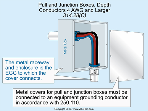
(C) Covers. Pull boxes and junction boxes must have a cover suitable for the conditions. Metal covers must be connected to an equipment grounding conductor of a type recognized in 250.118, in accordance with 250.110 [250.4(A)(3)]. ▶Figure 314“62
|
|
Figure 314“61 |
|
|
Figure 314“62 |
|
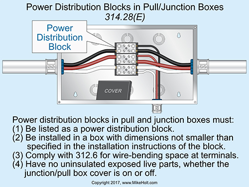
(E) Power Distribution Block. Power distribution blocks must comply with the following: ▶Figure 314“63
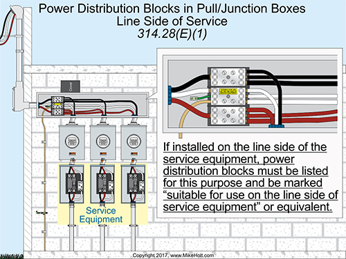
(1) Installation. Power distribution blocks must be listed; if installed on the line side of the service equipment, power distribution blocks must be listed and marked suitable for use on the line side of service equipment or equivalent. ▶Figure 314“64
(2) Size. Be installed in a box not smaller than required by the installation instructions of the power distribution block.
(3) Wire-Bending Space. The junction box is sized so the wire-bending space requirements of 312.6 can be met.
(4) Live Parts. Exposed live parts on the power distribution block aren't present when the junction box cover is removed.
(5) Through Conductors. Where the junction box has conductors that don't terminate on the power distribution block(s), the through conductors must be arranged so the power distribution block terminals are unobstructed following installation.
|
|
Figure 314“63 |
|
|
Figure 314“64 |
|
We'd love to hear from you about this series, and the ways you're using it. Send us your comments and feedback by clicking on Post a Comment below. Look out for the next part in this series a month from now, and please share with your colleagues.
This content is extracted from Mike Holt's Illustrated Guide to Understanding the 2017 National Electrical Code, Volume 2 textbook. If you have enjoyed this newsletter, you can get the full content in Mike's Understanding the NEC Complete Library here.
 |
LEARN MORE...
Purchase Mike's
Understanding the NEC Complete Library
(3 books | 12 DVDs)

For further information about this or other products please call us at 888.632.2633
We look forward to helping you
|
|
|
|