|
For EC&M Magazine
By Mike Holt, NEC® Consultant
Can you perform transformer calculations correctly every time?
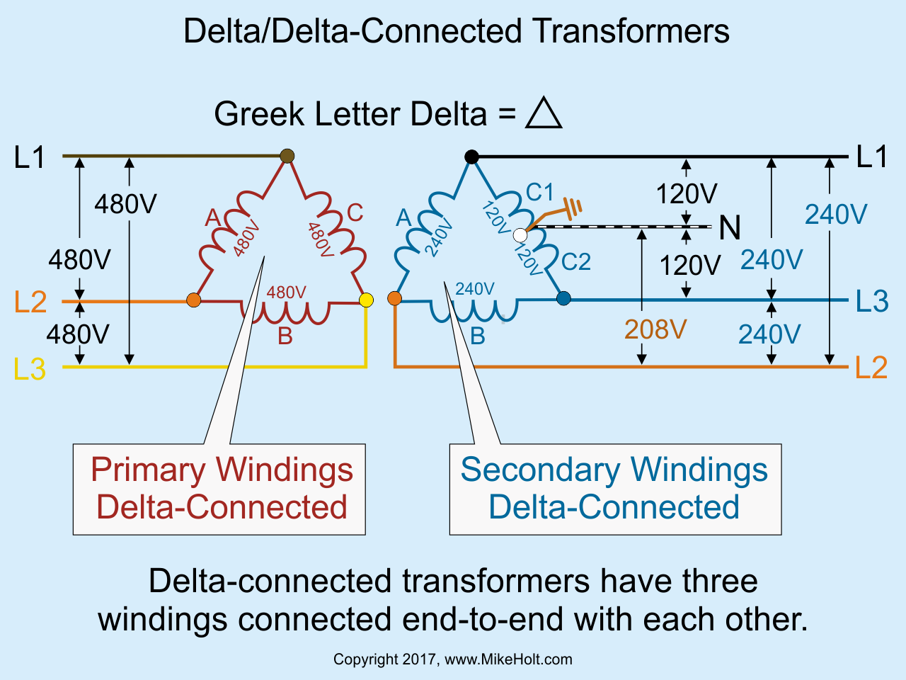
Figure 01
|
|
|
Figure 01
|
For EC&M Magazine
By Mike Holt, NEC® Consultant
Can you perform transformer calculations correctly every time?
A transformer transfers electrical energy (power) from one system to another by induction, with no physical connection between the two systems (other than grounding and bonding connections). Thus, the Code refers to transformers as separately derived systems.
Most transformers raise or lower voltage. But isolation transformers don't; they simply decouple the primary winding from the secondary winding.
Some basics
The transformer winding connected to the voltage source is the primary. The transformer winding connected to the load is the secondary.
The voltage that can be induced in the secondary winding from the primary magnetic field is a function of the number of secondary conductor loops (turns) cut by the primary electromagnetic field. The voltage on the primary side is the primary line voltage while the voltage on the secondary side is the secondary line voltage.
Transformers are rated in kilovolt-amperes (kVA), where 1 kilovolt-ampere = 1,000 volt-amperes (VA).
Delta and Wye
Delta-connected transformers have three windings connected end-to-end. The line conductors connect to each point where two windings meet. This system is called a Delta because when it's drawn out it looks like a triangle (the Greek symbol Delta for the letter D). For a delta/delta transformer, both the primary and secondary windings are delta connected.‚Figure 01
When working with delta transformers, don't forget about the high leg(Sidebar).
Wye-connected transformers have one lead from each of three windings connected to a common point. The other leads from each of the windings connect to the line conductors. A wye-configured secondary is often represented with a Y-shaped arrangement of the windings.‚
Line currents
You can calculate the line current of a transformer by using the appropriate formula for single-phase or three-phase systems:
Single-phase: †I = VA/E†
Three-phase: †I = VA/(E × 1.732)†
Overcurrent protection
To protect the windings of a transformer against overcurrent, use the percentages listed in Table 450.3(B) and its applicable notes.
Section 450.3(B) covers the protection of the transformer windings, not the conductors supplying or leaving the transformer.
For currents of 9A or more, 450.3(B) Note 1 applies. Where 125 percent of the primary current doesn't correspond to a standard fuse or nonadjustable circuit breaker, you can use the next higher rating of overcurrent protective device (OCPD), as listed in 240.6(A).
Primary overcurrent protection, less than 9A example
Question: What's the maximum primary OCPD rating for a 2 kVA (2,000 VA) continuously loaded, single-phase, 240V transformer?
(a) 4.81A (b) 5.31A (c) 13.92A (d) 17.12A
Answer: (c) 13.92A
Primary Current = Transformer VA Rating/Primary Voltage†
Primary Current = 2,000 VA/240V
Primary Current = 8.33A
Primary Protection = Primary Current × Table 450.3(B)††Percentage†
Primary Protection = 8.33A × 167%
Primary Protection = 13.92A
Primary overcurrent protection, greater than 9A example
Question: What's the maximum primary OCPD rating for a 45 kVA (45,000 VA) continuously loaded, three-phase, 480V transformer?‚
(a) 40A (b) 50A (c) 60A (d) 70A
Answer: (d) 70A
Primary Current =† †Transformer VA Rating/(Primary Voltage × 1.732)†
Primary Current = 45,000 VA/(480V × 1.732)
Primary Current = 54A
Primary Protection =††Primary Current × Table 450.3(B) Percentage†
Primary Protection = 54A × 125%
Primary Protection = 68A; use a 70A OCPD [240.6(A) and Table 450.3(B), Note 1]
Primary conductor sizing
Size the primary conductors at least 125 percent of the continuous loads, plus 100 percent of the noncontinuous loads, based on the terminal temperature rating ampacities as listed in Table 310.15(B)(16), before any ampacity adjustment [210.19(A)(1)].
Protect conductors against overcurrent per their ampacity after ampacity adjustment, as specified in 310.15 [240.4]. You can use the next higher standard rating of OCPD (above the ampacity of the conductors being protected) if the OCPD rating doesn't exceed 800A [240.4(B)].
Primary conductor sizing example
Question: What size primary conductor can be used for a 45 kVA (45,000 VA) continuously loaded, three-phase, 480V transformer, where the primary OCPD is sized at 70A?
(a) 6 AWG (b) 4 AWG (c) 3 AWG (d) 2 AWG
Answer: (b) 4 AWG
Step 1: Size the primary conductor at 125% of the primary current rating.
I = 45,000 VA/(480V × 1.732)
I = 54A
54A × 1.25 = 68A, 4 AWG, rated 70A at 60ºC
[110.14(C)(1)(a)(1), Table 310.15(B)(16)]
Step 2: Verify the conductors are protected per their ampacities [240.4].
4 AWG rated 70A at 60ºC can be protected by a 70A primary OCPD.
Secondary conductor sizing
The ampacity of the secondary conductor must at least the rating of the device supplied by the secondary conductors or the OCPD at the termination of the secondary conductors [240.21(C)(2)]. Assume the secondary conductors will carry the full capacity of the transformer continuously.
Step 1: Determine the rating of the device supplied by the secondary conductors at 125 percent of the secondary rating [215.2(A)(1)(a)].
Step 2: Size the secondary conductors so they have an ampacity of at least the device rating supplied by the secondary conductors [240.21(C)].
Secondary conductor sizing example
Question: What size secondary conductor can be used for a 45 kVA continuously loaded, three-phase, 480-120/208V transformer?
(a) 2 AWG (b) 1 AWG (c) 1/0 AWG (d) 2/0 AWG
Answer: (d) 2/0 AWG
Step 1: Determine the secondary current rating. ‰
Secondary Current = Transformer VA/††(Secondary Voltage × 1.732)†
I = 45,000 VA/(208V × 1.732)
I = 125A
Step 2: Size the secondary OCPD for continuous loading (125% of the secondary current rating) [215.3].‚
125A × 1.25 = 156A; use a 175A OCPD [240.6(A)]
Step 3: Size the secondary conductor so it has an ampacity of at least the 175A secondary OCPD (Step 2) [240.21(C)(2)].‚‰
2/0 AWG rated 175A at 75ºC [110.14(C)(1)(b), Table 310.15(B)(16)]
Grounding and bonding
A system bonding jumper, sized per 250.102(C) based on the area of the secondary conductors [250.30(A)(1) and 250.28(D)(1)], must be installed at the same location where the grounding electrode conductor terminates to the neutral point of a transformer [250.102(C)].
A grounding electrode conductor must connect the neutral point of a separately derived system to a grounding electrode of a type identified in 250.30(A)(4). Size the grounding electrode conductor per 250.66, based on the area of the ungrounded secondary conductor [250.30(A)(5)].
Avoiding errors
A calculation error can have disastrous results. So how can you reduce the chances of error in your transformer calculations?
The math involved isn't particularly challenging. But if you select the wrong formula, your results will be wrong even if your math is right. Taking four simple steps will help ensure you select the correct formula for a given application:
- Double-check the VA rating.
- Identify the primary and secondary voltages, and whether single phase or 3-phase.
- Double-check your load characterization and calculations.
- Check that you used the correct formulas. Here is a tip to help you do that without your eyes glazing over: reference the wrong formulas. For example, you're working in a single phase system. Look at the formula for a three-phase one, is this what you used? If not, great. Move on to the next item and use a similar process.
Sidebar: High leg
The terms high-leg, wild-leg, or stinger-leg identify the conductor (of a delta-connected system) that has a voltage of 208V to ground. The high-leg voltage is the vector sum of the voltage of transformers A and C1, or transformers B and C2, which equal 120V × 1.732 = 208V for a 120/240V secondary.
Some important NEC rules for high-legs:
- On a 4-wire, delta-connected, three-phase system, where the midpoint of one phase winding is grounded (high-leg system), the conductor with 208V to ground must be durably and permanently marked by an orange outer finish or other effective means [110.15]. Such identification must be at each point on the system where a connection is made if the neutral conductor is present [110.15 and 230.56].
- Since 1975, panelboards supplied by a 4-wire, delta-connected, three-phase system must have the high-leg conductor terminate to the B phase of a panelboard [408.3(E)(1)].
- The ANSI standard for meter equipment requires the high-leg conductor (208V to neutral) to terminate on the C (right) phase of the meter socket enclosure. This is because the demand meter needs 120V, and it receives that from the B phase.‚
- Section 408.3(F)(1) requires panelboards to be field-marked with Caution _____ Phase has _____ to Ground.
When replacing equipment in existing facilities that contain a high-leg conductor, ensure the high-leg conductor is replaced in the original location. Failure to re-terminate the high-leg per the existing installation can result in 120V circuits inadvertently connected to the 208V high-leg, with disastrous results.
|