|
By Mike Holt
NEC® Consultant for EC&M Magazine
Note: This article is based on the 2020 NEC.
A solid understanding of grounding electrode system requirements can prevent cost over-runs, Code violations, and performance failures.
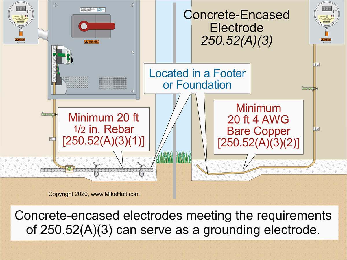
Figure 01
|
|
|
Figure 01
|
By Mike Holt
NEC® Consultant for EC&M Magazine
Note: This article is based on the 2020 NEC.
A solid understanding of grounding electrode system requirements can prevent cost over-runs, Code violations, and performance failures.
To create a grounding electrode system, you bond the various electrodes that are present. By electrodes we mean those described in 250.52(A)(1) through (A)(7).
Of course, you can't bond something like conductive steel reinforcing bars that are inaccessible without chipping up the concrete so there's an exception for that [250.68(A) Ex1].
Electrode types
Underground metal water pipe in direct contact with the Earth for 10 ft or more can serve as a grounding electrode [250.52(A)(1)]. But should it? Controversy over this issue has existed since the early 1900s. The water industry believes neutral current flowing on water piping corrodes the metal.
Metal in-ground support structure(s) in direct contact with the Earth vertically for 10 ft or more can serve as a grounding electrode [250.52(A)(2)]. These structures include pilings, casings, and other structural metal.
Concrete-encased electrodes meeting the requirements of this subsection can serve as grounding electrodes [250.52(A)(3)]. Figure 01
(1) One or more electrically conductive steel reinforcing bars (rebar) of at least ½ in. in diameter that are mechanically connected by steel tie wires to create a 20 ft or greater length can serve as a grounding electrode.
(2) A bare copper conductor at least 4 AWG and at least 20 ft long can serve as a grounding electrode.
The rebar or bare copper conductor must be encased by at least 2 in. of concrete in direct contact with the Earth. Where multiple concrete-encased electrodes are present at a building, only one must serve as a grounding electrode.
Rebar in concrete that is not in direct contact with the Earth because of insulation, vapor barriers, or similar items is not considered to be a concrete-encased electrode.
A grounding electrode conductor to a concrete-encased grounding electrode is not required to be larger than 4 AWG copper [250.66(B)]. See sidebar.
A direct buried bare copper conductor at least 2 AWG encircling a building can serve as a grounding electrode 250.52(A)(4)]. A ground ring encircling a building must be at least 30 in. below the surface [250.53(F)].
A ground rod is an obvious choice for a grounding electrode [250.52(A)(5)]. It must have at least 8 ft in length in contact with the Earth and have a diameter of at least 5/8 in., unless listed.
If the grounding electrode conductor is the sole connection to the rod(s), it is not required to be larger than 6 AWG copper [250.66(A)]. The diameter of a ground rod has an insignificant effect on the contact resistance of a rod(s) to the Earth. However, larger diameter rods (¾ in. and 1 in.) are sometimes installed where mechanical strength is desired, or to compensate for the loss of the electrode metal from corrosion.
Other listed grounding electrodes can serve as a grounding electrode [250.52(A)(6)].
A bare or electrically conductive coated iron or steel plate least ¼ in. thick, or a solid uncoated copper metal plate at least 0.06 in. thick, with an exposed surface area of at least 2 sq ft can serve as a grounding electrode 250.52(A)(7)].
Metal underground systems, piping, and well casings can serve as a grounding electrode 250.52(A)(8)]. The grounding electrode conductor to the metal underground system must be sized per Table 250.66, based on the area of the largest phase conductor.
Prohibited uses
You can't use any of these as a grounding electrode [250.52(B)]:
(1) Underground metal gas piping.
(2) Aluminum.
(3) The swimming pool structural reinforcing steel described in 680.26(B)(1) and (B)(2).
Installation requirements
If practicable, rod, pipe, and plate electrodes must be embedded below the permanent moisture level and free from nonconductive coatings such as paint or enamel [250.53(A)(1)].
A single ground rod must be supplemented by an additional electrode [250.53(A)(2)]. The supplemental electrode must be bonded to:
(1) Another ground rod
(2) The grounding electrode conductor
(3) The service neutral conductor
(4) A nonflexible metal service raceway
(5) The service-disconnect enclosure
Ex: A single ground rod electrode having a contact resistance to the Earth of 25 ohms or less does not require a supplemental electrode.
The supplemental electrode must be at least 6 ft from the ground rod [250.53(A)(3)].
The electrode must be installed such that at least 8 ft of length touches the soil. It must be driven to at least 8 ft deep. So, it must be driven pretty much vertical.
What if you encounter a rock bottom? In that case, you can:
- Drive the electrode at an oblique angle of up to 45 degrees from the vertical, or
- Bury it in a trench at least 30 in. deep [250.53(A)(4)].
The upper end of the ground rod must be flush with or below ground level unless the grounding electrode conductor attachment is protected against physical damage as specified in 250.10.
When the grounding electrode attachment fitting is below ground level, it must be listed for direct soil burial [250.70].
Electrodes for premises systems must be at least 6 ft from lightning protection system grounding electrodes [250.53(B)]. Two or more grounding electrodes bonded together are considered a single grounding electrode system.
Grounding electrode bonding jumpers used to connect the grounding electrodes together must be copper when within 18 in. of the Earth [250.64(A)]. Exposed grounding electrode bonding jumpers must be securely fastened to the surface and protected from physical damage [250.64(B)]. Size the bonding jumper to each electrode per 250.66, based on the area of the largest phase conductor [250.53(C)].
Grounding electrode bonding jumpers must terminate using one of the eight means identified in 250.8(A), such as listed pressure connectors or terminal bars. When the grounding electrode conductor termination is encased in concrete or buried, the termination fittings must be listed for this purpose [250.70]. You cannot use rebar to interconnect the electrodes of grounding electrodes systems (it's not a copper grounding conductor) [250.53(C)].
Continuity of the grounding path or the bonding connection to interior piping must not rely on water meters, filtering devices, or similar equipment [250.53(D)(1)].
When an underground metal water pipe grounding electrode is present, it must be supplemented by one of the following electrodes [250.53(D)(2)]:
- Metal frame of the building electrode [250.52(A)(2)].
- Concrete-encased electrode [250.52(A)(3)].
- Rod electrode [250.52(A)(5)].
- Other type of listed electrode [250.52(A)(6)].
- Metal underground piping electrode [250.52(A)(8)].
If the supplemental electrode is a rod or plate type, it must comply with 250.53(A). The supplemental electrode must be bonded to one of the following:
(1) Grounding electrode conductor.
(2) Service neutral conductor.
(3) Nonflexible metal service raceway.
(4) Service-disconnect enclosure.
Because a metal underground water pipe electrode could be replaced by a plastic water pipe, the supplemental electrode must be installed as if it is the only electrode for the system. Ex: The supplemental electrode can be bonded to interior metal water piping not more than 5 ft from the point of entrance to the building as specified in 250.68(C)(1).
The grounding electrode conductor to a ground rod that serves as a supplemental electrode is not required to be larger than 6 AWG copper [250.53(E)].
A ground ring encircling a building must be a bare 2 AWG or larger copper conductor installed at least 30 in. below the surface [250.52(A)(4)].
Avoiding errors
Most errors with grounding electrode systems result from designing or installing the system without a clear overview of the components and how they should interconnect to provide a path to ground. To get this clear overview, draw out the system.
Old-timers often sketch it out by hand on sheet of paper. This isn't because of a lack of computer skills, but because this method forces you to think it out as you go. Draw the electrodes first, then draw the bonding jumpers that connect them. Ensure each electrode is one of the eight types in 250.52(A) and each bonding jumper complies with 250.53(C).
Sidebar: Ufer Ground
A concrete-encased grounding electrode is also called a Ufer Ground. Herbert G. Ufer was a consultant working for the U.S. Army during World War II. One of his projects involved a series of bomb storage vaults near Flagstaff, Arizona.
The desert site had no underground water table and little rainfall. The technique Ufer developed overcame both of these problems. This type of grounding electrode generally offers the lowest ground resistance for the cost. Mr. Ufer's method is so effective that no other ground rods are necessary.
|