|
By Mike Holt
NEC® Consultant for EC&M Magazine
Note: This article is based on the 2020 NEC.
Do you know the requirements for grounding electrodes and grounding electrode conductors?
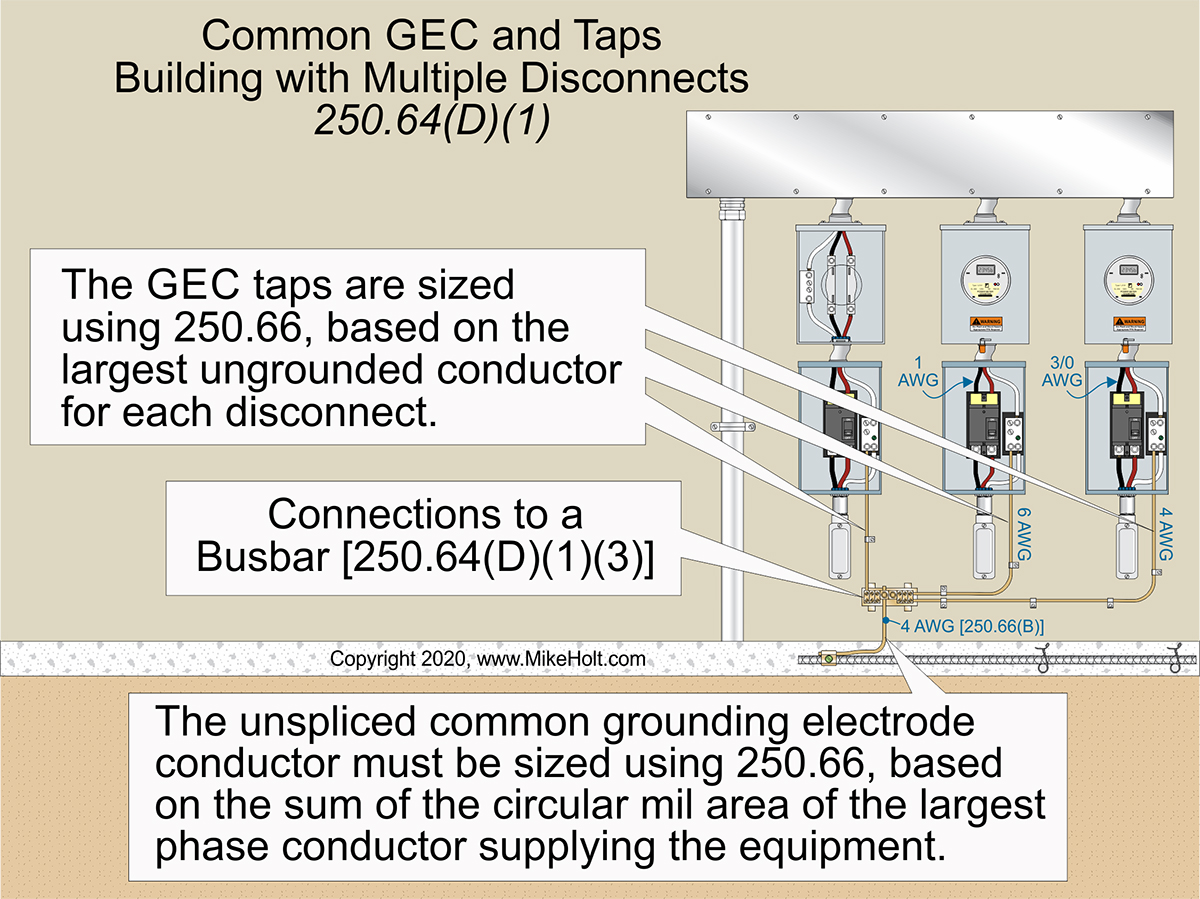
Figure 01
|
|
|
Figure 01
|
By Mike Holt
NEC® Consultant for EC&M Magazine
Note: This article is based on the 2020 NEC.
Do you know the requirements for grounding electrodes and grounding electrode conductors?
Where more than one alternating-current system connects to a grounding electrode at a building, the same grounding electrode must be used for all systems [250.58].
Potentially dangerous objectionable neutral current flows on the metal parts of an electrical system when multiple service disconnects are connected to the same electrode. This is because neutral current from each service can return to the utility via the common grounding electrode and its conductors. It's especially a problem if a service neutral conductor is open.
Grounding electrode conductors
Grounding electrode conductors (GECs) of the wire type must be copper if within 18 in. of the earth [250.64(A)]. GECs must be installed as specified in 250.64(A) through (F):
(A) Aluminum and copper-clad GECs must comply with the following:
(1) Conductors without an extruded polymeric covering cannot be installed where subject to corrosive conditions or in direct contact with concrete.
(2) Terminations made within listed enclosures identified for outdoor use are permitted within 18 in. of the bottom of the enclosure. If open-bottom enclosures are installed on a concrete pad, the concrete is not considered earth.
(3) Aluminum or copper-clad conductors external to buildings or equipment enclosures cannot be terminated within 18 in. of the earth.
(B) Where exposed, a GEC must be securely fastened to the surface on which it is carried. GECs can be installed on or through framing members.
(1) GECs 6 AWG and larger can be installed exposed along the surface of the building if securely fastened and not exposed to physical damage.
(2) GECs subject to physical damage must be protected in rigid metal conduit (RMC), intermediate metal conduit (IMC), Schedule 80 rigid polyvinyl chloride conduit (PVC), reinforced thermosetting resin conduit Type XW (RTRC-XW), electrical metallic tubing (EMT), or cable armor.
(3) GECs smaller than 6 AWG must be protected in RMC, IMC, Schedule 80 PVC, RTRC-XW, EMT, or cable armor.
(4) GECs and bonding jumpers in contact with the earth are not required to comply with the cover requirements of 300.5 but must be protected where subject to physical damage.
(C) GEC(s) must be installed without a splice or joint except by:
(1) Irreversible compression-type connectors or exothermic welding.
(2) Busbars connected together.
(3) Bolted, riveted, or welded connections of the structural metal frames of buildings.
(4) Threaded, welded, brazed, soldered, or bolted-flange connections of metal water piping.
(D) If a building contains two or more service or feeder disconnects in separate enclosures, the grounding electrode connections must be made by one of the following methods:
(1) For common GEC and taps, size the unspliced common GEC per 250.66, based on the sum of the circular mil area of the largest phase conductor supplying the equipment. Figure 01
A GEC tap must extend from each disconnect and must be sized no smaller than specified in Table 250.66, based on the area of the largest phase conductor.
The GEC tap must be connected to the common GEC by exothermic welding, connectors listed as grounding and bonding equipment, or connections to a busbar.
If connections to a busbar, the tap must be of sufficient length, at least ¼ in. thick × 2 in. wide, securely fastened, and installed in an accessible location. Aluminum busbars must comply with 250.64(A) [250.64(D)(1)(3).
(2) An individual GEC from each disconnect sized per 250.66, based on the phase conductor(s) supplying the individual disconnect, must connect the grounding electrode system to one of the following:
(1) The service neutral conductor.
(2) The equipment grounding conductor of the feeder circuit.
(3) The supply-side bonding jumper.
(3) In buildings with multiple disconnecting means, a GEC from an accessible enclosure, such as meter enclosures and wireways on the supply side of the disconnects, sized per 250.66 and based on the phase conductor(s) supplying the disconnect, must connect the grounding electrode system to one of the following:
(1) The service neutral conductor.
(2) The equipment grounding conductor of the feeder circuit.
(3) The supply-side bonding jumper.
(E) To prevent inductive choking of GECs, each end of ferrous metal raceways, enclosures, and cable armor containing GECs must be bonded to the GEC. Raceway bonding must be per 250.92(B)(2) through (B)(4). Bonding jumpers must be at least the size of the largest GEC in the raceway or other enclosure.
(F) A single GEC can terminate to any grounding electrode of the grounding electrode system. Where multiple GECs are installed [250.64(D)(2)], each one can terminate to any electrode of the grounding electrode system in .
Sizing GECs
Except as permitted in 250.66(A) through (C), size GECs per Table 250.66, based on the area of the largest phase conductor. If a GEC or bonding jumper connects to only a:
(A) Ground rod [250.52(A)(5)], it doesn't have to be larger than 6 AWG copper.
(B) Concrete-encased electrode [250.52(A)(3)], it doesn't have to be larger than 4 AWG copper.
(C) Ground ring [250.52(A)(4)], it doesn't have to be larger than the conductor used for the ground ring.
Connection to grounding electrodes
The mechanical elements used to terminate a GEC or bonding jumper to a grounding electrode must be accessible [250.68(A)].
Ex 1: The termination doesn't have to be accessible if the termination to the electrode is encased in concrete or buried in the earth.
Ex 2: Exothermic or irreversible compression connections, together with the mechanical means used to attach to fireproofed structural metal, don't have to be accessible.
A bonding jumper must be installed around insulated joints and equipment likely to be disconnected for repairs or replacement for an underground metal water piping system used as a grounding electrode [250.68(B)]. The bonding jumper must be of sufficient length to allow the removal of such equipment while retaining the integrity of the grounding path.
GECs and bonding jumpers can terminate at the following locations and be used to extend the connection to an electrode(s) [250.68(C)]:
(1) Interior metal water piping that is electrically continuous with a metal underground water pipe electrode and is not more than 5 ft from the point of entrance can be used to extend the connection to electrodes. Interior metal water piping more than 5 ft from the point of entrance cannot be used as a conductor to interconnect electrodes of the grounding electrode system.
(2) The metal structural frame of a building can be used to interconnect electrodes that are part of the grounding electrode system, or as a GEC where the hold-down bolts secure the structural steel column to a concrete-encased electrode [250.52(A)(3)]. The hold‘down bolts must be connected to the concrete-encased electrode by welding, exothermic welding, the usual steel tie wires, or other approved means.
(3) A rebar-type concrete-encased electrode [250.52(A)(3)] with rebar extended to an accessible location above the concrete foundation or footing is permitted, but the rebar extension:
(a) Must be continuous with the grounding electrode rebar or must be connected to the grounding electrode rebar and connected together by the usual steel tie wires, exothermic welding, welding, or other effective means.
(b) Cannot be in contact with the earth or subject to corrosion.
(c) Cannot be used as a conductor to interconnect the electrodes of grounding electrode systems.
GEC termination fittings
The GEC must terminate to the grounding electrode by exothermic welding, listed lugs, listed pressure connectors, listed clamps, or other listed means. In addition, fittings terminating to a grounding electrode must be listed for the grounding electrode and the GEC [250.70].
When the termination to a grounding electrode is buried in the earth or encased in concrete, the termination fitting must be listed for direct soil burial or concrete encasement.
No more than one conductor can terminate on a single clamp or fitting unless the clamp or fitting is listed for multiple connections.
Why grounding electrode systems matter
Earth is not the effective ground-fault current path specified in 250.4(A)(5). Because the contact resistance of an electrode to the earth is so great, only a tiny portion of fault current returns to the power supply if the earth is the only fault current return path.
Consequently, the circuit overcurrent protective device will not open and clear the ground fault. And all metal parts associated with the electrical installation, metal piping, and structural building steel will become and remain energized. You need something far more conductive than the earth.
 |
Learn More...
Get Your Copy of Mike's
Bonding and Grounding Program
(1 book | 4 DVDs)

For further information
about this or other products please call us at
888.632.2633
|
|
|