|
For EC&M Magazine
By Mike Holt, NEC® Consultant
Here's the follow-up to yesterday's newsletter.
This includes the answers to the questions sent, so you can see how you did.

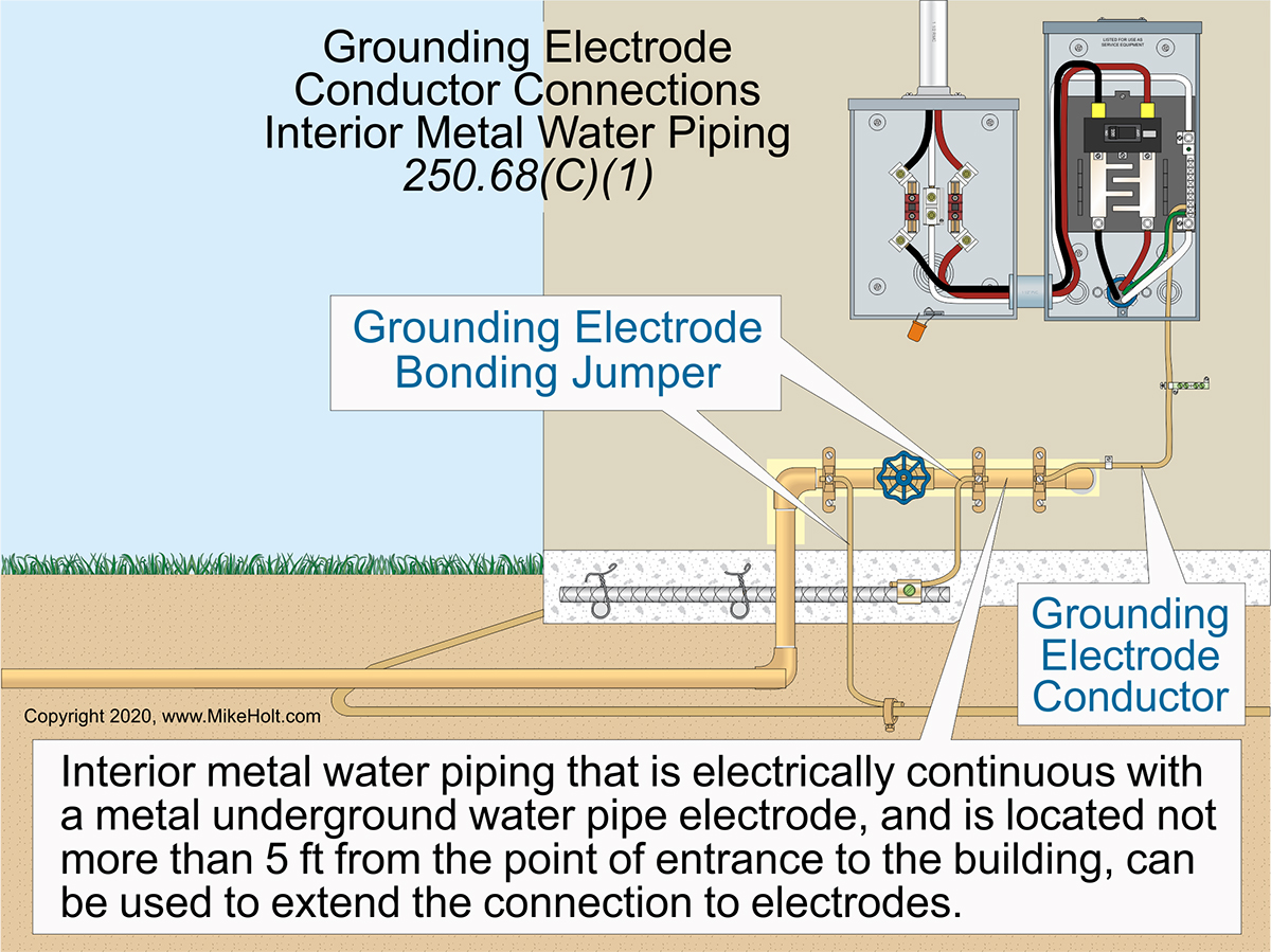
Figure 01
|
|
|
Figure 01
|
For EC&M Magazine
By Mike Holt, NEC® Consultant
Here's the follow-up to yesterday's newsletter.
This includes the answers to the questions sent, so you can see how you did.
Note: The answers to these questions are based on the 2020 NEC.
Q1. What is the Code rule regarding the installation of grounding electrode conductors?
A1. Grounding electrode conductors must be installed as specified in (A) through (F) [250.64].
(A) Aluminum and Copper-Clad Aluminum Conductors. Bare, covered, or insulated aluminum or copper-clad grounding electrode conductors must comply with the following:
(1) Bare or covered conductors without an extruded polymeric covering are not permitted
to be installed where subject to corrosive conditions or to be installed in direct contact with concrete.
(2) Terminations made within listed enclosures identified for outdoor use are permitted
within 18 in. of the bottom of the enclosure.
Author's Comment:
►If open-bottom enclosures are installed on a concrete pad, the concrete is not considered earth.
(3) Aluminum or copper-clad aluminum conductors external to buildings or equipment enclosures are not permitted to be terminated within 18 in. of the earth.
(B) Conductor Protection. Where exposed, a grounding electrode conductor must be securely
fastened to the surface on which it is carried. Grounding electrode conductors can be installed on or through framing members.
(1) Not Exposed to Physical Damage. Grounding electrode conductors 6 AWG and larger can be installed exposed along the surface of the building if securely fastened and not exposed
to physical damage.
(2) Exposed to Physical Damage. Grounding electrode conductors subject to physical damage
must be protected in rigid metal conduit (RMC), intermediate metal conduit (IMC), Schedule 80 rigid polyvinyl chloride conduit (PVC), reinforced thermosetting resin conduit Type XW (RTRC-XW), electrical metallic tubing (EMT), or cable armor.
(3) Smaller Than 6 AWG. Grounding electrode conductors smaller than 6 AWG must
be protected in RMC, IMC, Schedule 80 PVC, RTRC-XW, EMT, or cable armor.
Author's Comment:
► While Table 250.66 permits the use of 8 AWG copper as the grounding electrode conductor for the phase conductor sizes typically used for a 100A service, use of a GEC smaller than 6 AWG is not common.
(4) In Contact with the Earth. Grounding electrode conductors and bonding jumpers in contact with the earth are not required to comply with the cover requirements of 300.5 but must be protected where subject to physical damage.
(C) Continuous. Grounding electrode conductor(s) must be installed without a splice or joint except by:
(1) Irreversible compression-type connectors or exothermic welding.
(2) Busbars connected together.
(3) Bolted, riveted, or welded connections of structural metal frames of buildings.
(4) Threaded, welded, brazed, soldered, or bolted-flange connections of metal water piping.
(D) Grounding Electrode Conductor for Multiple Building Disconnect Enclosures. If a building contains two or more service or feeder disconnects in separate enclosures, the grounding electrode connections must be made by any of the following methods:
(1) Common Grounding Electrode Conductor and Taps. The unspliced common grounding electrode conductor must be sized in accordance with 250.66 based on the sum of the circular mil area of the largest phase conductor supplying the equipment.‚
A grounding electrode conductor tap must extend from each disconnect, and it must be sized no smaller than specified in Table 250.66 based on the area of the largest phase conductor.
The grounding electrode conductor tap must be connected to the common grounding electrode conductor by any of the following methods:
(1) Exothermic welding.
(2) Connectors listed as grounding and bonding equipment.
(3) Connections to a busbar of sufficient length and not less than ¼ in. thick × 2 in. wide that is securely fastened and installed in an accessible location.
(2) Individual Grounding Electrode Conductors. An individual grounding electrode conductor from each disconnect, sized in accordance with 250.66 based on the phase conductor(s) supplying the individual disconnect, must connect the grounding electrode system to one of the following:
(1) The service neutral conductor
(2) The equipment grounding conductor of the feeder circuit
(3) The supply-side bonding jumper
(3) Supply Side of Disconnects. A grounding electrode conductor from an accessible enclosure on the supply side of the disconnects, sized in accordance with 250.66 and based on the phase conductor(s) supplying the disconnect, must connect the grounding electrode system to one of the following:
(1) The service neutral conductor
(2) The equipment grounding conductor of the feeder circuit
(3) The supply-side bonding jumper
(E) Ferrous Raceways Contining Grounding Electrode Conductors
(1) General. To prevent inductive choking of grounding electrode conductors, ferrous metal raceways, enclosures, and cable armor containing grounding electrode conductors must have each end of the raceway or enclosure bonded to the grounding electrode conductor.
(2) Methods. Raceway bonding must be done in accordance with 250.92(B)(2) through (B)(4).
(3) Size. Bonding jumpers must be the same size or larger than the largest grounding electrode conductor in the raceway or other enclosure.
Author's Comment:
►Nonferrous metal raceways, such as aluminum rigid metal conduit, enclosing the grounding electrode conductor are not required to meet the bonding each end of the raceway to the grounding electrode conductor provisions of this section.
►To save a lot of time and effort, install the grounding electrode conductor in a nonmetallic raceway suitable for the application. Schedule 40 PVC can be used for exposed work but Schedule 80 PVC is required in areas subject to physical damage [352.10(F)].
Q2. What are the Code requirements when connecting grounding electrode conductors and bonding jumpers to grounding electrodes?
A2. Grounding Electrode Conductor Connections. Grounding electrode conductors and bonding jumpers are permitted to terminate at the following locations and be used to extend the connection to an electrode(s) [250.68(C)]:
(1) Interior metal water piping that is electrically continuous with a metal underground water pipe electrode and is located not more than 5 ft from the point of entrance to the building can be used to extend the connection to electrodes. Interior metal water piping located more than 5 ft from the point of entrance to the building is not permitted to be used as a conductor to interconnect electrodes of the grounding electrode system.Figure 01
(2) The metal structural frame of a building can be used as a conductor to interconnect electrodes that are part of the grounding electrode system, or as a grounding electrode conductor where the hold-down bolts secure the structural steel column to a concrete-encased electrode [250.52(A)(3)]. The hold-down bolts must be connected to the concrete-encased electrode by welding, exothermic welding, the usual steel tie wires, or other approved means.
(3) A rebar-type concrete-encased electrode [250.52(A)(3)] with rebar extended to an accessible location above the concrete foundation or footing is permitted under the following conditions:
(a) The additional rebar section must be continuous with the grounding electrode rebar or must be connected to the grounding electrode rebar [250.52(A)(3)] and connected together by the usual steel tie wires, exothermic welding, welding, or other effective means.
(b) The rebar extension is not permitted to be in contact with the earth.
(c) The rebar extension is not permitted to be used as a conductor to interconnect the electrodes of grounding electrode systems.
Author's Comment:
►The most commonly specified type of rebar becomes very brittle where subjected to heat. Welding or exothermic welding to that type of rebar may not be identified for such use. Check with the structural engineer before making a connection with that type to rebar.
►Rebar located outdoors could be subject to corrosion.
Q3. What Code rule allows the use of metal enclosures for connecting bonding jumpers and equipment grounding conductors as part of the effective ground-fault current path?
A3. Metal enclosures can be used to connect bonding jumpers or equipment grounding conductors, or both, together to become a part of an effective ground-fault current path. Metal covers and metal fittings attached to these metal enclosures are considered as being connected to bonding jumpers or equipment grounding conductors, or both [250.109].
Q4. What Code rule requires the connection of a receptacle grounding terminal to an equipment grounding conductor?
A4. An equipment bonding jumper sized in accordance with Table 250.122 is required to connect the grounding contacts of a receptacle to a metal box that is connected to an equipment grounding conductor, except as permitted in (A) through (D) [250.146].
Author's Comment:
►The NEC does not restrict the position of the receptacle grounding terminal; it can be up, down, or sideways. Code proposals to specify the mounting position of receptacles have always been rejected.
(A) Surface-Mounted Box. A receptacle having direct metal-to-metal contact between the receptacle strap or yoke and a surface metal box is considered to be connected to the required effective ground-fault current path. To ensure sufficient metal-to-metal contact, at least one of the insulating retaining washers on the yoke screw must be removed.
A receptacle installed on a cover is considered to be connected to the required effective ground-fault current path under both of the following conditions:
(1) The receptacle is attached to the metal cover with at least two fasteners that have a thread locking, or screw or nut locking means.
(2) The cover mounting holes are located on a flat non-raised portion of the cover.
(B) Self-Grounding Receptacles. Receptacle yokes listed as self-grounding establish the equipment bonding between the receptacle yoke and a metal box.
(C) Floor Boxes. Listed metal floor boxes must establish the bonding path between the receptacle yoke and a metal box.
(D) Isolated Ground Receptacles. The grounding terminal of an isolated ground receptacle must be connected to an insulated equipment grounding conductor.
Informational Note: Use of an isolated equipment grounding conductor does not relieve the requirement for connecting the raceway system and outlet box to an equipment grounding conductor.
Author's Comment:
►Type AC cable containing an insulated equipment grounding conductor can be used to supply isolated ground receptacles because the metal armor of the cable is listed as an equipment grounding conductor [250.118(8)].
Author's Comment:
►Interlocked Type MCAP® cable with a 10 AWG bare aluminum grounding/bonding conductor can be used to supply isolated ground receptacles because the combination of the metal armor and the 10 AWG bare aluminum conductor is listed as an equipment grounding conductor [250.118(10)(b)].

 Type MC Cable. The metal armor sheath of traditional interlocked Type MC cable containing an insulated equipment grounding conductor is not listed as an equipment grounding conductor. Therefore, this wiring method with a single equipment grounding conductor cannot supply an isolated ground receptacle. Type MC cable with two insulated equipment grounding conductors is acceptable, since one bonds to the metal box and the other one connects to the isolated ground receptacle. Type MC Cable. The metal armor sheath of traditional interlocked Type MC cable containing an insulated equipment grounding conductor is not listed as an equipment grounding conductor. Therefore, this wiring method with a single equipment grounding conductor cannot supply an isolated ground receptacle. Type MC cable with two insulated equipment grounding conductors is acceptable, since one bonds to the metal box and the other one connects to the isolated ground receptacle.
Author's Comment:
►When should an isolated ground receptacle be installed and how should the isolated ground system be designed? These questions are design issues and are not answered based on the NEC alone [90.1(A)]. In most cases, using isolated ground receptacles is a waste of money. For example, IEEE 1100, Powering and Grounding Electronic Equipment (Emerald Book) states, The results from the use of the isolated ground method range from no observable effects, the desired effects, or worse noise conditions than when standard equipment bonding configurations are used to serve electronic load equipment [8.5.3.2].
►Few electrical installations truly require an isolated ground system. For those systems that can benefit from one, engineering opinions differ as to what is a proper design. Making matters worse”of those properly designed, few are correctly installed, and even fewer are properly maintained.
Q5. What Code rule addresses the continuity and attachment of equipment grounding conductors in boxes?
A5. Equipment grounding conductors associated with circuit conductors that are spliced or terminated on equipment within a box must be connected within the box or to the box in accordance with 250.8 and 250.148(A) through (D) [250.148].
Ex: The circuit equipment grounding conductor for an isolated ground receptacle [250.146(D)] is not required to be connected to the other equipment grounding conductors or to the metal box.
(A) Connections and Splices. Equipment grounding conductors must be connected and spliced with a device identified for the purpose in accordance with 110.14(B).
(B) Continuity of Equipment Grounding Conductors. Equipment grounding conductors must terminate in such a manner that the disconnection or the removal of a receptacle, luminaire, or other device will not interrupt the electrical continuity of the equipment grounding conductor(s) providing an effective ground-fault current path.
(C) Metal Boxes. Equipment grounding conductors for circuit conductors that are spliced or terminated on equipment within a metal box must be spliced together [250.148] and have a connection to the metal box in accordance with 250.8.
Author's Comment:
►Equipment grounding conductors are not permitted to terminate to a screw that secures a plaster ring or by drywall screws used to secure the box.
(D) Nonmetallic Boxes. Equipment grounding conductors in a nonmetallic outlet box must be arranged such that a connection can be made to any fitting or device in that box requiring connection to an equipment grounding conductor.
|