|
By Mike Holt
NEC® Consultant for EC&M Magazine
Note: This article is based on the 2020 NEC.
Do you know how to correctly size and install equipment grounding conductors?
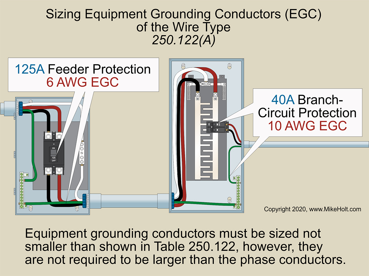
Figure 01
|
|
|
Figure 01
|
By Mike Holt
NEC® Consultant for EC&M Magazine
Note: This article is based on the 2020 NEC.
Do you know how to correctly size and install equipment grounding conductors?
Good workmanship is an NEC requirement [110.12] that people often associate with how the completed work looks. But when you install an equipment grounding conductor (ECG) good workmanship includes more than just the things you can see when the work is complete. The fittings and terminations for raceways, cable trays, cable armor, cablebus framework, or cable sheaths must be made tight using suitable tools [250.120(A)] and the correct methods.
Exposed EGCs 8 AWG and smaller for direct-current circuits [250.134 Ex.2], such as required by 690.45 for solar PV systems, can be run separately from the circuit conductors. Where the 8 AWG or smaller exposed EGC is subject to physical damage, it must be installed within a identified raceway or cable armor [250.120(C)].
Aluminum and Copper-Clad Aluminum EGCs
The requirements for EGCs that are bare, covered, or insulated aluminum and copper-clad aluminum are in 250.120(B):
You cannot install bare or covered aluminum or copper-clad aluminum conductors where subject to corrosive conditions or in direct contact with concrete, masonry, or earth, unless they are part of a suitable Chapter 3 wiring method.
Terminations made within outdoor enclosures that are listed and identified for the environment are permitted within 18 in. of the bottom of the enclosure. If open-bottom enclosures are installed on a concrete pad, the concrete is not considered earth.
Aluminum conductors external to buildings or enclosures cannot be terminated within 18 in. of the earth, unless terminated within a listed wire connector system.
Restricted use of EGCs
You can’t use an EGC as a grounding electrode conductor [250.121(A)]. Ex: If an EGC meets the requirements for an EGC and grounding electrode conductor, you can use it as both a EGC and grounding electrode conductor.
You can’t use the structural metal frame of a building as an EGC [250.121(B)]. Here is a perfect example of why it is so important you completely understand the terminology used throughout the Code. While the structural metal frame of a building can’t be used as an “EGC,” it can be used as a conductor to interconnect grounding electrodes [250.68(C)(2)]. Knowing the difference is what makes the difference!
Sizing EGCs of the Wire Type
If your EGC is the raceway or cable tray containing the conductors (rather than a wire-type EGC), it will be larger than the phase conductors and you don’t need to bother with the table. So when we are talking about sizing EGCs, we mean wire-type EGCs. If you use both raceway and wire-type EGC enclosed within, the size requirements still apply to the wire-type EGC.
EGCs must be sized not smaller than shown in Table 250.122; however, the EGC is not required to be larger than the phase conductors [250.122(A)]. Figure 01
Phase conductors are sometimes increased in size to accommodate conductor voltage drop, short-circuit rating, or future capacity. If phase conductors are increased in size for any reason other than as required in 310.15(B) or 310.15(C), wire-type EGCs, if installed, must be increased in size proportionately to the increase in the circular mil area of the phase conductors [250.122(A)].
Ex: EGCs can be sized by a qualified person to provide an effective ground-fault current path per 250.4(A)(5) or (B)(4).
Example
Question: If the phase conductors for a 40A circuit (with 75ºC terminals) are increased in size from 8 AWG to 6 AWG due to voltage drop, the circuit EGC must be increased in size from 10 AWG to _____.
(a) 8 AWG (b) 6 AWG (c) 4 AWG (d) 3 AWG
Solution:
The circular mil area of 6 AWG is 59 percent more than 8 AWG (26,240 cmil/16,510 cmil) [Chapter 9, Table 8]. According to Table 250.122, the circuit EGC for a 40A overcurrent protective device will be 10 AWG (10,380 cmil), but the circuit EGC for this circuit must be increased in size by a multiplier of 159 percent.
Conductor Size = 10,380 cmil × 159%
Conductor Size = 16,504 cmil
The circuit EGC must be increased to 8 AWG [Chapter 9, Table 8].
Answer: (a) 8 AWG
You can use a single EGC sized per Table 250.122 when multiple circuits are installed in the same raceway, cable, trench, or cable tray [250.122(C)].
EGCs for motors
You must size EGCs for motor circuits per 250.122(D)(1) or (D)(2).
For motor circuits, follow 250.122(D)(1). The EGC must not be smaller than determined by 250.122(A), based on the rating of the motor circuit branch-circuit short-circuit and ground-fault protective device sized per 430.52(C)(1) Ex 1.
The EGC is not required to be larger than the motor circuit conductors. See 250.122(A).
Example
Question: What size EGC of the wire type is required for a 14 AWG motor branch circuit [430.22], protected with a 2‑pole, 40A circuit breaker per 430.22 and 430.52(C)(1)?
(a) 14 AWG (b) 12 AWG (c) 10 AWG (d) 8 AWG
Solution:
The EGC is not required to be larger than the 14 AWG motor branch-circuit conductors [250.122(D)(1) and 250.122(A)].
Answer: (a) 14 AWG
Parallel conductors
The 2020 revision has changed the requirements for when circuit conductors are installed in parallel per 310.10(G). If parallel circuit conductors are installed in:
- A single nonmetallic raceway or cable tray, you must install a single wire-type EGC (sized per Table 250.122 based on the rating of the circuit overcurrent protective device) with the parallel circuit conductors [250.122(F)(1)(a)].
- Multiple nonmetallic raceways, you must install a wire-type EGC in each raceway [250.122(F)(1)(b)]. Size each one per Table 250.122 based on the rating of the circuit overcurrent protective device.
Example
Question: What size copper EGC of the wire type is required for a 4,000A feeder containing thirteen parallel sets of 500 kcmil aluminum conductors per phase in PVC conduit?
(a) 250 kcmil copper (b) 300 kcmil copper
(c) 400 kcmil copper (d) 500 kcmil copper
Solution:
According to Table 250.122, the copper EGC in each raceway must not be smaller than 500 kcmil copper.
Answer: (d) 500 kcmil copper
Cable trays and raceways
Wire-type EGCs installed in cable trays must meet the minimum requirements of 392.10(B)(1)(c) [250.122(F)(1)(c)]. Metal raceways can serve as the required EGC per 250.118 and cable trays complying with 392.60(B) can serve as the required EGC. [250.122(F)(1)(d)].
Parallel multiconductor cables
The EGC in each multiconductor cable must be sized per 250.122, based on the overcurrent protective device for the feeder or branch circuit [250.122(F)(2)(a)].
If circuit conductors of multiconductor cables are connected in parallel, the EGC(s) in each cable must be connected in parallel [250.122(F)(2)(b)].
If multiconductor cables are paralleled in the same raceway or cable tray, a single EGC sized per 250.122 is permitted in combination with the EGCs provided within the multiconductor cables and all EGCs must be connected together [250.122(F)(2)(c)].
EGCs installed in cable trays must meet the requirements of 392.10(B)(1)(c) [250.122(F)(2)(d)]. Cable trays complying with 392.60(B) and metal raceways per 250.118 can be used as the required EGC.
Feeder Tap Conductors
EGCs for feeder taps are not permitted to be smaller than shown in Table 250.122, based on the ampere rating of the overcurrent device ahead of the feeder on the supply side of the tap [250.122(G)]. The feeder EGC for the feeder tap is not required to be larger than the tap conductors.
Getting EGC size right
Before you start dealing with the EGC part of a project, take a moment to recognize that you’re not grounding anything. The “grounding” terminology is left over from when the NEC poorly defined terms related to bonding and grounding.
An equipment grounding conductor (EGC) is actually an equipment bonding conductor. It forms a metallic path not to the earth (grounding, as defined in Article 100) but back to the source. Recall that where a wire EGC is required, it’s run with the phase conductors instead of to a ground rod.
Because the EGC must be able to carry the fault current back to the source, its size matters. It matters relative to the current-carrying conductors. Whether you use the NEC tables to manually determine ECG sizes or a software program that automatically calculates ECG sizes, check to make sure the resulting numbers make sense.
|