By Mike Holt
NEC® Consultant for EC&M Magazine
Note: This article is based on the 2020 NEC.
If your installation is a “Special Occupancy”, Chapter 5 requirements affect how you implement Article 250.
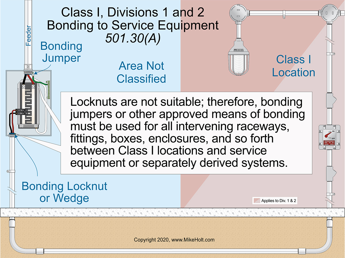
Figure 01
|
|
|
Figure 01
|
By Mike Holt
NEC® Consultant for EC&M Magazine
Note: This article is based on the 2020 NEC.
If your installation is a “Special Occupancy”, Chapter 5 requirements affect how you implement Article 250.
For bonding and grounding, six articles from Chapter 5 are of particular note:
- Article 501—Class I Hazardous (Classified) Locations. Flammable or combustible liquid-produced vapors or flammable gases may present the hazard of a fire or explosion.
- Article 502—Class II Hazardous (Classified) Locations. Combustible dust may present the hazard of a fire or explosion.
- Article 503—Class III Hazardous (Classified) Locations. Easily ignitible fibers/flyings may present the hazard of a fire or explosion.
- Article 517—Health Care Facilities. Human health care facilities such as hospitals, nursing homes, clinics, medical and dental offices, and ambulatory care—whether permanent or movable.
- Article 547—Agricultural Buildings. Buildings, parts of buildings, or adjacent areas, used in agriculture where excessive dust may accumulate or where a corrosive atmosphere exists.
- Article 555—Marinas, Boatyards, Floating Buildings, and Commercial and Noncommercial Docking Facilities. Areas comprised of fixed or floating piers, wharves, docks, and other areas in marinas, boatyards, boat basins, boathouses, and similar locations intended for the repair, berthing, launching, storing, or fueling of small craft, and the mooring of floating buildings.
Articles 501, 502, and 503—Class I, II, and III Locations
Bonding in hazardous classified locations is intended to provide a low impedance path to clear a fault that will be free from arcing due to loose connections at fittigns or terminations. The special bonding requirements are the same for all three Classes of location. Here, we use Article 501 as the reference.
Because of the explosive conditions associated with electrical installations in hazardous locations [500.5], electrical continuity of metal parts of equipment and raceways must be ensured regardless of the circuit voltage [501.30 (see also 502.30 and 503.30)].
Locknuts are unsuitable for bonding in hazardous locations; therefore, bonding jumpers or other approved means of bonding must be used for all raceways, fittings, boxes, enclosures, etc. between Class I locations and service equipment or separately derived systems [501.30(A)]. Figure 01
Regardless of the circuit voltage, electrical continuity of the metal parts of equipment and raceways in hazardous locations must be ensured by the use bonding-type locknuts, wedges, or bushings with bonding jumpers [250.92(B)(4)]; whether or not equipment grounding conductors of the wire type are installed in the raceway [250.100]. Locknuts alone are not enough to serve this purpose.
A separate equipment grounding conductor (EGC) is not required if a metal raceway is used for equipment grounding. Threaded couplings and hubs made up wrenchtight provide a suitable low-impedance fault current path [250.92(B)(2)].
Where flexible metal conduit or liquidtight flexible metal conduit is installed as permitted by 501.10(B)(2), an equipment bonding jumper of the wire type must be installed per 250.102 [501.30(B)].
Size bonding jumpers per Table 250.122, based on the rating of the overcurrent protective device [250.102(D)]. Where installed outside a raceway, the bonding jumpers cannot exceed 6 ft long and they must be routed with the raceway [250.102(E)(2)].
Article 517—Health Care Facilities
Patient care spaces, as designated by the facility administrator, include patient rooms, examining rooms, therapy areas, treatment rooms, and some patient corridors. They do not include business offices, corridors, lounges, dining rooms, or similar areas not classified as patient care spaces [517.2].
Equipment grounding requirements in patient care spaces are based on the concept of two different types of equipment grounding conductors so if there is an installation error, the effective ground-fault current paths are not lost.
One type of EGC is “mechanical” (the wiring method), and the other is of the “wire type.” Section 517.13(A) requires the wiring method to be a metal raceway or metal cable that qualifies as an EGC per 250.118. Section 517.13(B) requires an insulated copper EGC of the wire type per 250.118.
Branch-circuit conductors serving patient care spaces must be in a metal raceway or metal cable having a metal sheath that qualifies as an EGC per 250.118 [517.13(A)].
The metal sheath of traditional Type MC interlocked cable does not qualify as an EGC [250.118(10)(a)]; therefore, this wiring method cannot be used for circuits in patient care spaces.
The metal sheath of Type AC cable is identified as an EGC in 250.118(8) because it contains an internal bonding strip in direct contact with the metal sheath of the interlocked cable.
The following equipment must be directly connected to an insulated copper EGC that has green insulation along its entire length. Such conductors must be contained in a suitable wiring method as required in 517.13(A).
(1) The grounding contact of receptacles, other than isolated ground (IG) receptacles, must be directly connected to a green insulated copper EGC [517.13(B)(1)(1)].
(2) Metal enclosures containing circuit conductors must be directly connected to a green insulated copper EGC [517.13(B)(1)(2)].
(3) Noncurrent-carrying metal parts of fixed electrical equipment must be directly connected to an insulated copper EGC [517.13(B)(1)(3)].
(4) Metal faceplates must be connected to the circuit EGC by means of a metal mounting screw(s) securing the faceplate to a metal yoke or strap of a receptacle, or to a metal outlet box [517.13(B)(1)(4)].
Ex 2: Circuits for luminaires more than 7½ ft above the floor and switches outside the patient care vicinity must be installed in a 517.13(A) wiring method; an insulated copper EGC of the wire type is not required within the wiring method.
Size EGCs and equipment bonding jumpers per 250.122 [517.13(B)(2)].
An IG receptacle, if used, must not defeat the safety features of the grounding systems detailed in 517.13. Do not install an IG receptacle within a patient care vicinity [517.16(A)].
IG receptacle(s) within the patient care space (as defined in 517.2), but outside the patient care vicinity, must comply with the following [517.16(B)]:
(1) The equipment grounding terminal of IG receptacles must connect to an insulated EGC per 250.146(D) and be installed in a wiring method described in 517.13(A). The EGC connected to the equipment grounding terminals of the IG receptacle must have green insulation with one or more yellow stripes along its entire length.
(2) The insulated EGC required by 517.13(B)(1) must connect to the metal enclosure containing the receptacle as required by 517.13(B)(1)(2).
The EGC of isolated ground receptacles doesn’t provide the benefits of the multiple equipment grounding paths required in 517.13 because the equipment grounding terminal is isolated form the yoke of the device. For that reason, IG receptacles can’t be installed in a patient care vicinity but are allowed in a patient care space if the installation complies with 517.13(A) and (B) and the isolated EGC is identified by green insulation with one or more yellow stripes.
Installing isolated equipment grounding conductors is done in addition to establishing a low impedance effective ground fault path back to the supply source with the raceway system and outlet box.
Article 547—Agricultural Buildings
Where the EGC is not part of a listed cable assembly, it must be insulated when installed underground [547.5(F)].
Equipotential planes must be installed in livestock confinement areas (indoors or outdoors) if those areas include concrete floors where metallic equipment that is accessible to livestock and that may become energized [547.10(A)].
The equipotential plane must be connected to the building electrical grounding system with a solid copper bonding conductor (insulated, covered, or bare) at least 8 AWG using pressure connectors or clamps approved by the authority having jurisdiction [547.10(B)].
The bonding requirements in Article 547 are unique because livestock can be sensitive to small voltage differences between areas within animal confinement areas, especially in wet or damp concrete. Usually the voltage difference between metal parts and the Earth will be too low to present a shock hazard to people. However, livestock might detect the voltage difference if they come into contact with the metal parts. Although voltage differences may not be life threatening to them, reports show as little as 0.50V RMS can reduce milk production in dairy animals.
Article 555—Marinas, Boatyards, and Docking Facilities
Metal parts in contact with the water, metal piping, and noncurrent-carrying metal parts likely to become energized must be connected to the grounding bus in the panelboard using a solid copper conductor (insulated, covered, or bare) at least 8 AWG [555.13]. Make all bonding connections to these metal parts per 250.8.
The following items must be connected to an EGC run with the circuit conductors in the same raceway, cable, or trench [555.37(A)]:
(1) Metal boxes, metal cabinets, and all other metal enclosures.
(2) Metal frames of utilization equipment.
(3) Grounding terminals of grounding-type receptacles.
The EGC must be an insulated conductor with a continuous outer finish that is either green or green with one or more yellow stripes [555.37(B)]. Size the insulated EGC per 250.122, but at least 12 AWG [555.37(C)].
The insulated EGC for branch circuits must terminate at a grounding terminal in a remote panelboard or the grounding terminal in the main service equipment [555.37(D)].
Where a feeder supplies a remote panelboard, an insulated EGC must extend from a grounding terminal in the service equipment to a grounding terminal in the remote panelboard [555.37(E)].
Special rules
Rules that limit installation practices, like prohibiting the use of traditional Type MC interlocked cable for circuits in patient care spaces, exist because of special concerns for the use of that space. The wiring method and EGC used in patient care spaces [517.13] must both protect the patient from injury or death while they are being treated and may not be able to protect themselves.
As you can see the rules for a given special occupancy stem from concepts particular to that type of occupancy. Once you can understand the concepts behind the rules, you can apply those rules more consistently and with confidence.
|