- About Us
- Contact Us
- Testimonials
- Continuing Education
- Approved Courses
- Course Login
- Electrical Engineer PDHs
- ICC Approved Courses
- Live CEU Seminars
- NABCEP CEUs
- Electrical Engineering
- Electrical Engineer PDHs
- Engineers Library
- Exam Preparation
- Florida State Exam Prep
- Inspector (Electrical)
- Journeyman Exam Prep
- Masters Exam Prep
- State Licensing Boards
- Free Stuff
- Charts & Calculators
- Code Forum
- Find an Expert
- Find a School
- Graphic of the Day
- Job Board
- Links
- NEC
- Newsletters
- Publications
- Podcasts
- Technical
- Videos
- Instructors & Schools
- Apprenticeship
- Capacitor Login
- ISBNs
- Training Solutions
- Request a Quote
- Products
- Best Values
- Books & DVDs
- Clearance
- Seminars
- CEU Seminars
- Seminar Schedule


Technical Resources
FREERESOURCES

![]()
We strive to provide the electrical industry with resources that will guide , inspire and educate you to become the best that you can be. Our goal with this page is to make it easy for you to find the information that you need in one place. Remember, when it comes to things electrical, don’t guess or think—research, learn and make sure that you have the FACTS.
Bonding & Grounding
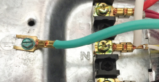
Articles, Code Forum, newsletters and videos
Business Management

Articles, Code Forum, newsletters
Calculations
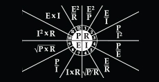
Articles, Code Forum, newsletters and videos
Electrical Theory

Code Forum and videos
Engineering
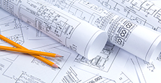
Articles, Code Forum and links
Estimating

Code Forum and estimating software
Lightning/ Surge Protection
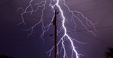
Articles, Code Forum, links and newsletters
Low Voltage

Code Forum, links and newsletters
Marinas & Boatyards

Articles, newsletters and resources
National Electrical Code

Code Forum, newsletters, NEC questions, state adoptions and videos
Power Quality
Articles, Code Forum, links and newsletters
Safety
Articles, Code Forum, links, newsletters and videos
Solar Photovoltaics

Code Forum, links, newsletters and videos
Stray Voltage

Articles, Code Forum, links, newsletters and videos
Swimming Pools

How to verify the electrical system of a pool is safe in accordance with the NEC
Underwriters Laboratories

UL Articles